Antenna Rotor - Part 2
 Written by
Lucas Teske
Written by
Lucas Teske
on
Continuing the tracker project, I managed to make some significant progress. As Demilson (PY2UEP) had cut the original motors, I did the same. The azimuth motor was too rusted and I eventually destroyed one of the coils (which I wanted to salvage the wire), but in the end the shaft went out.
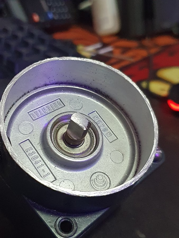
After removing the shaft, I broke the magnet with a hammer until there was any piece left. That way, the only thing that would be left there is the shaft and the hexagon magnet support.
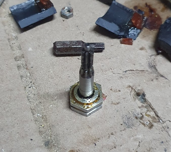
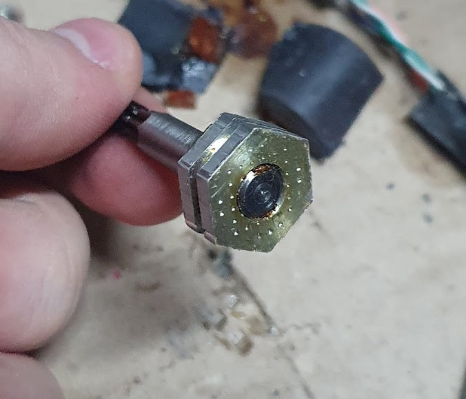
 Motor shaft showing the hexagon support
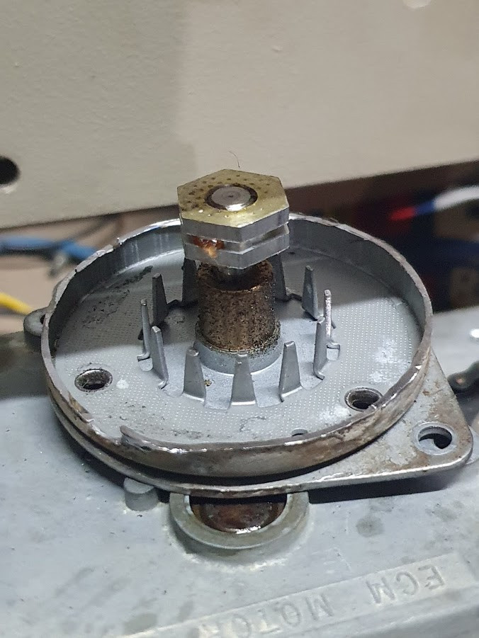
For the elevation motor, I made a cut in a circular mark around the exit of the shaft. That way I could use the same support for coupling with the reduction gears.
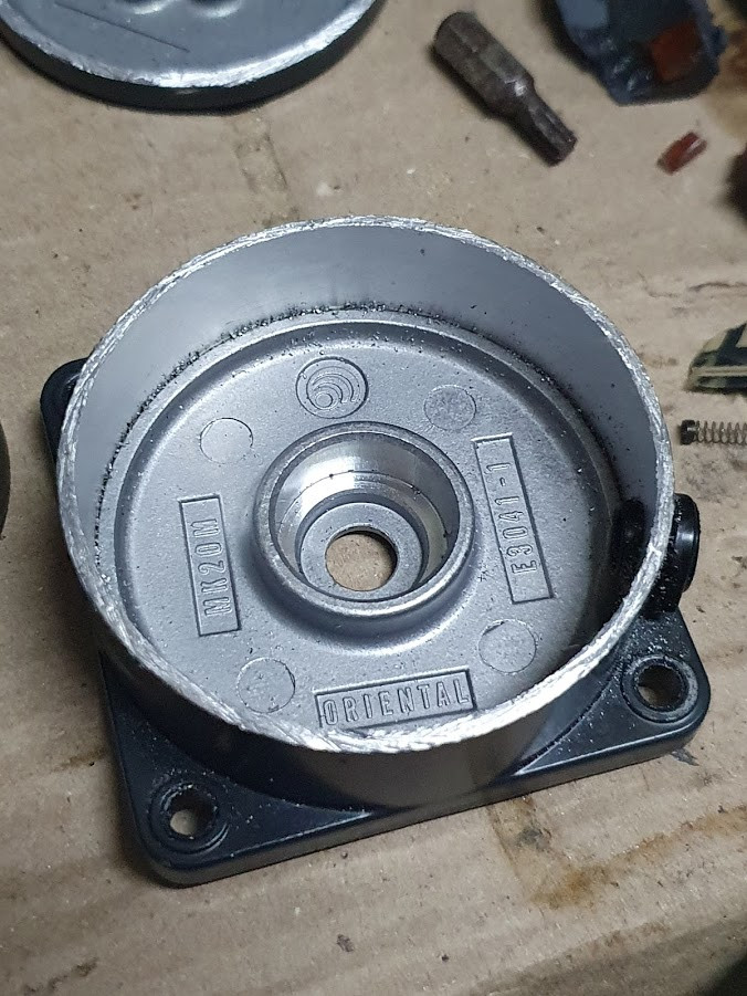 “lid” of the elevation motor after cut
 Lid + Reduction Gears
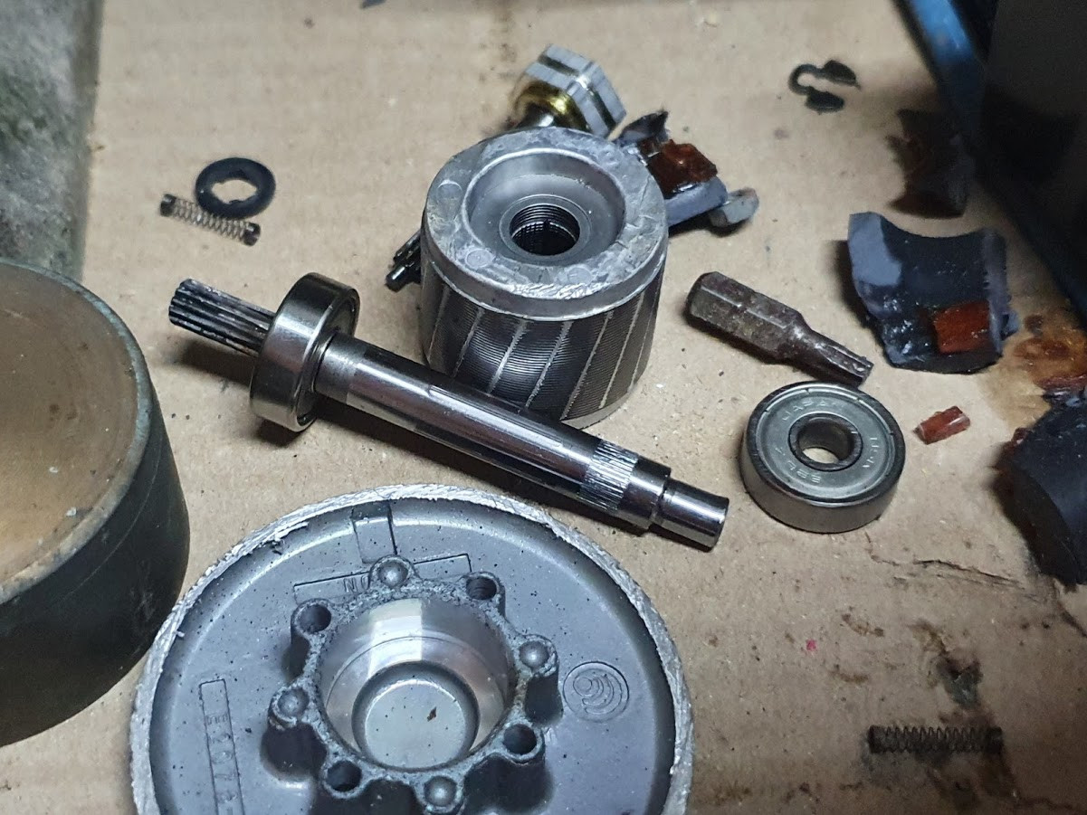 Motor Pieces
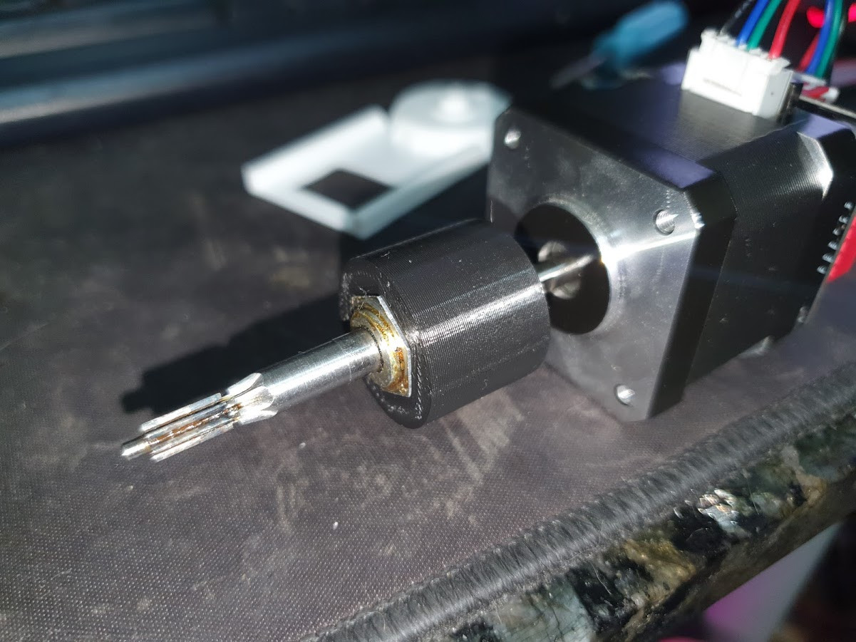
For the shaft, it was nescessary to reduce its size and made a bevel so I could fit it better in a 3D Printed part. To do so, I use two plywood pieces to hold the shaft while me and my father cut it. For the bevel, we used a grinder.
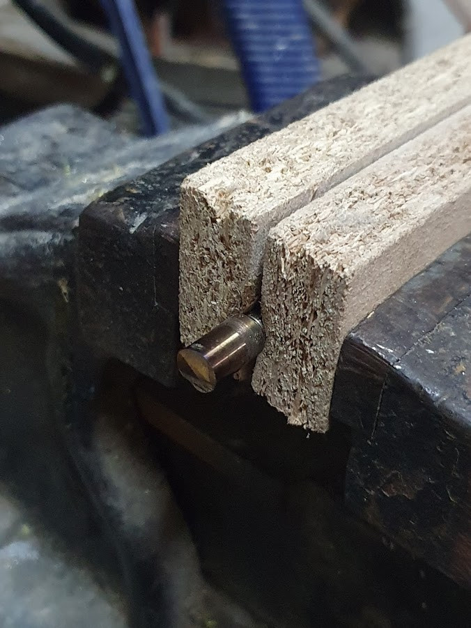 Plywood and cut shaft
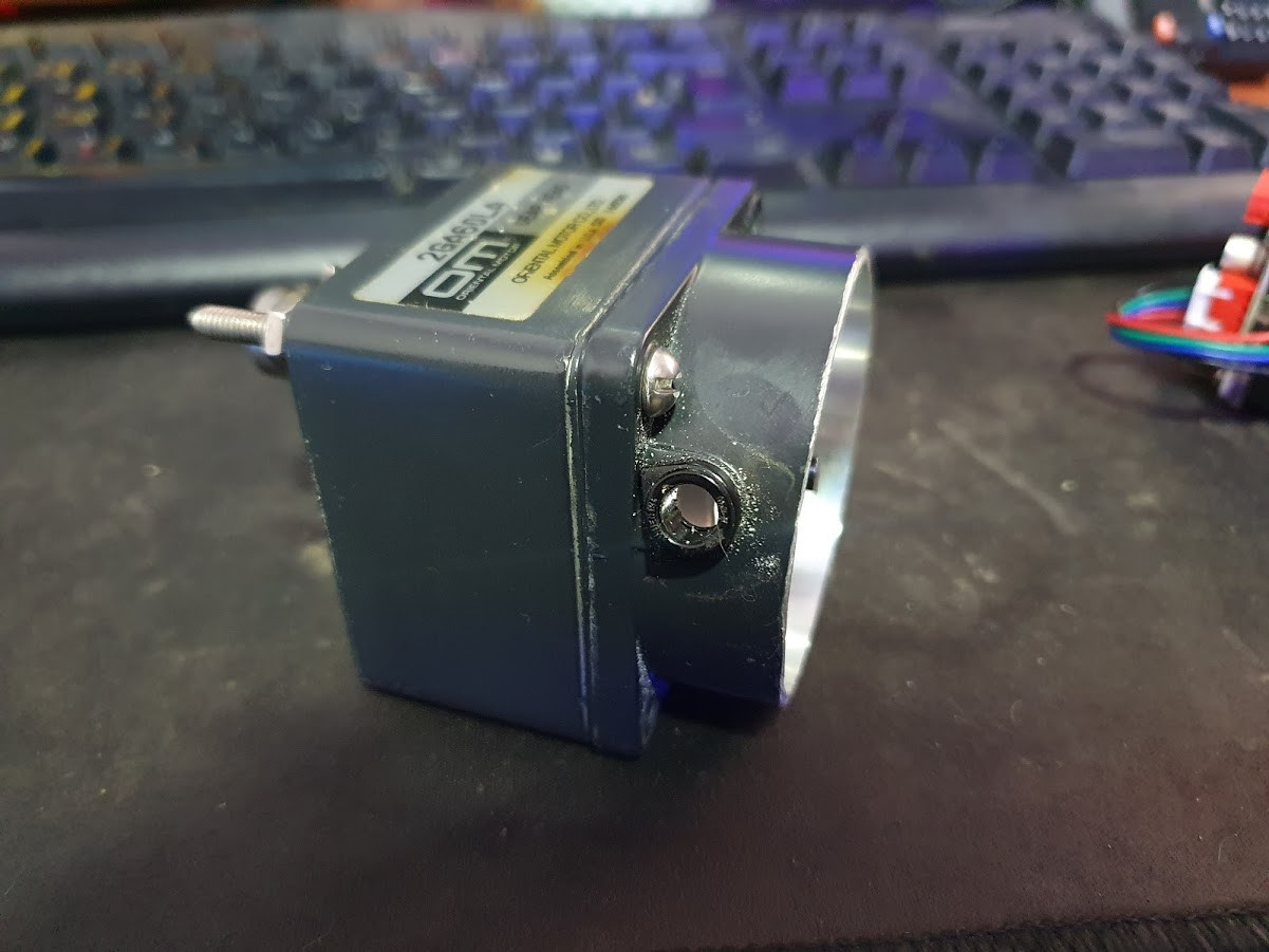
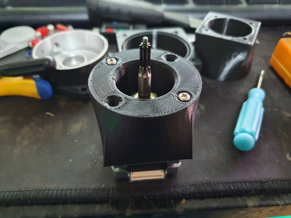
 Cut shaft on motor head
With that, I could then start the 3D Drawings for the adapters.
3D Prints
After A LOT of trial and error, I managed to make good fittings between the shafts. But then I realized a problem: The space for the azimuth axis was extremelly limited, in the way that my 40 mm NEMA17 motors were too big for it.
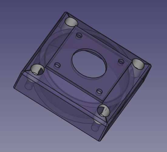
 Azimuth Adapter
Then I had to buy some “slim” motors to use in that place. I got a bit concerned with the final torque, but my attempts to make gears and other stuff were all failed. The motors I bought in Aliexpress (see links in the end of this post)
While the motor wasn’t arriving, I started optimizing the adapters to be the shortest as possible, saving all space I could. I use FreeCAD for being free and where I can do faster / better drawings. But don’t assume I’m a 3D Designer, because I’m not. My parts are only “functional”.
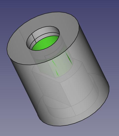
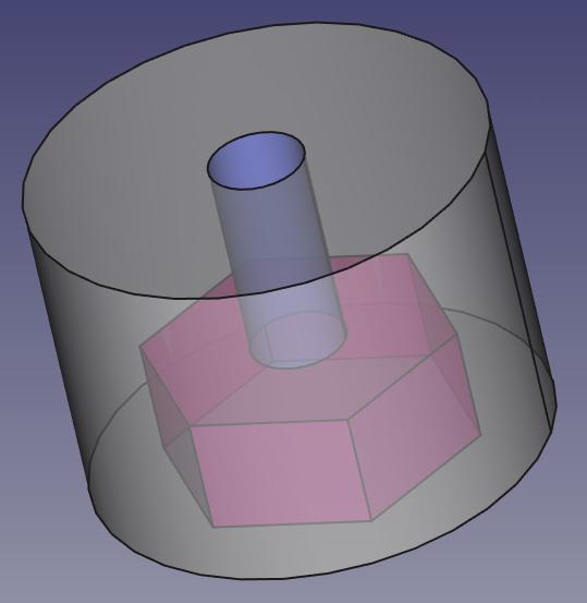 Azimuth Shaft Adapter
 Azimuth Support
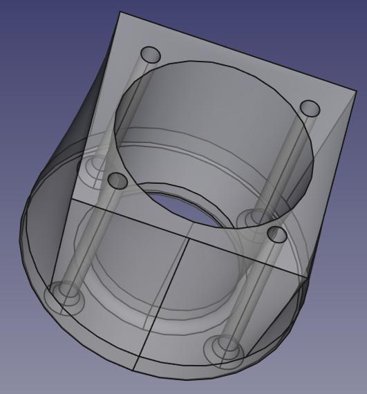
 Elevation Shaft Adapter
 Elevation Adapter
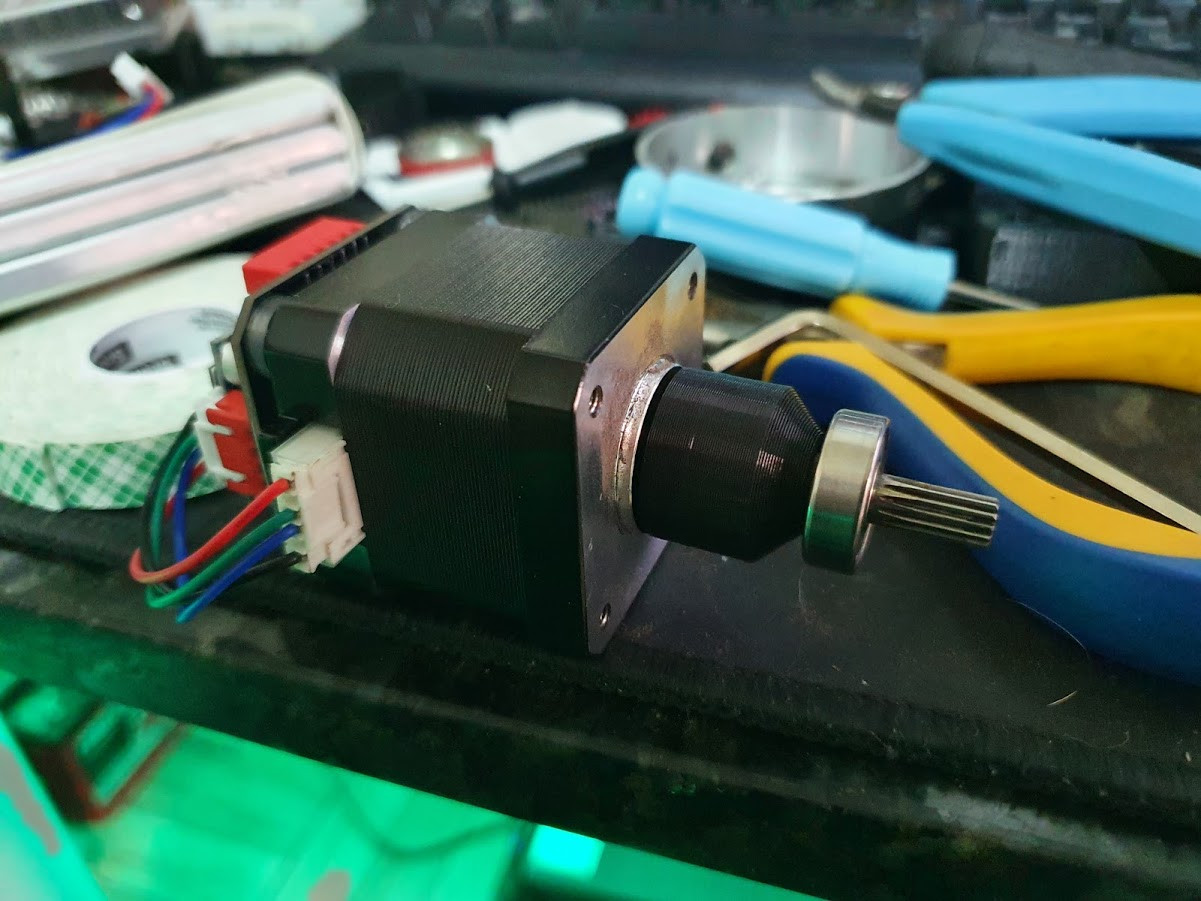
And the first axis to work was the elevation. To do so I used 40 mm NEMA17 motors (link in end of this post), which came with a closed-loop magnetic encoder driver. But in the end I went to use a TMC2209 to control instead the board that came in because it was easier and quieter.
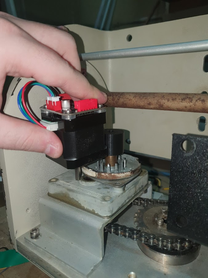
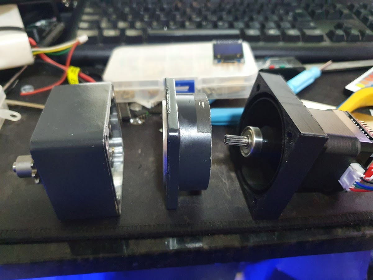
After the new azimuth motors arrived, I just tried to fit everything. And it did! se ia caber. E coube!
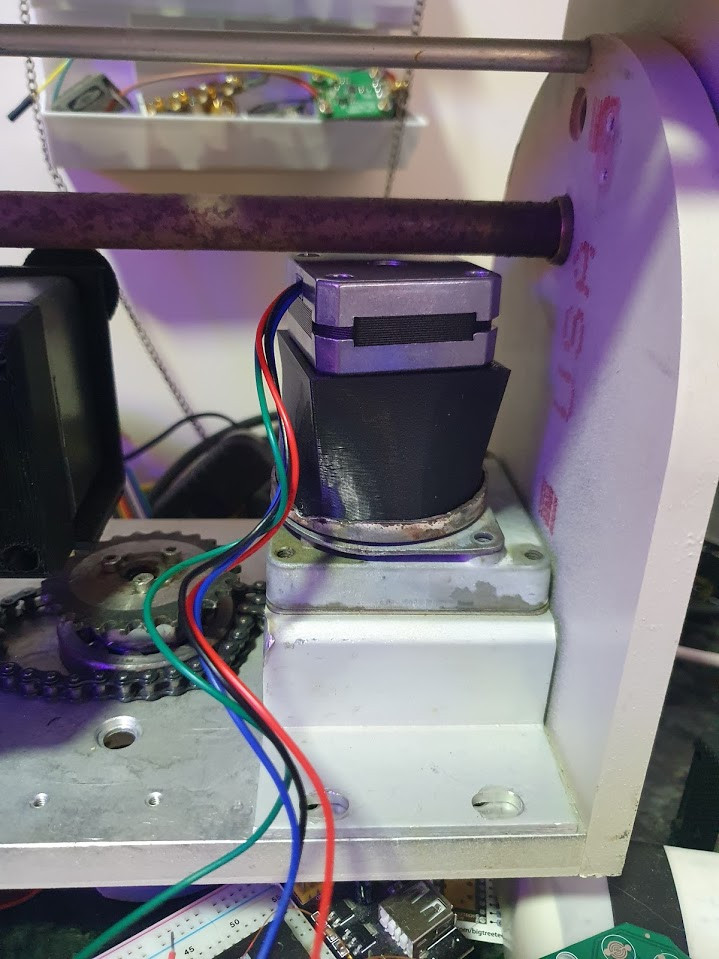
And also working!
After everything was working, I did some tests to check what was the final resolution and reduction for both axis. To do so, I used the following code with an ESP32 to control the TMC2209 drivers, and for angle measurement I used my phone attached to the elevation base.
#include <TMCStepper.h>

#define STEP_PIN         12 // Step
#define EN_PIN           23 // Enable

#define SERIAL_PORT Serial2 // TMC2208/TMC2224 HardwareSerial port
#define DRIVER_ADDRESS 0b00 // TMC2209 Driver address according to MS1 and MS2

#define R_SENSE 0.11f

TMC2209Stepper driver(&SERIAL_PORT, R_SENSE, DRIVER_ADDRESS);

void setup() {
  pinMode(STEP_PIN, OUTPUT);
  pinMode(EN_PIN, OUTPUT);
  digitalWrite(EN_PIN, LOW);

  SERIAL_PORT.begin(115200);      // HW UART drivers
  Serial.begin(115200);

  driver.begin();                 // UART: Init SW UART (if selected) with default 115200 baudrate
  driver.toff(10);                // Enables driver in software
  driver.rms_current(1000);       // Set motor RMS current
  driver.microsteps(2);           // Set microsteps to 1/16th

  driver.en_spreadCycle(false);    // Toggle spreadCycle on TMC2208/2209/2224
  driver.pwm_autoscale(true);      // Needed for stealthChop

  Serial.println("OK");
  digitalWrite(EN_PIN, HIGH);
}

bool shaft = false;

void loop() {
//  Serial.println("TURN");
  if (Serial.available() > 0) {
    int z = Serial.read();
    if (z == 'a') {
      Serial.println("Stepping 10000");
      digitalWrite(EN_PIN, LOW);
      for (uint32_t i = 10000; i>0; i--) {
        digitalWrite(STEP_PIN, HIGH);
        delayMicroseconds(350);
        digitalWrite(STEP_PIN, LOW);
        delayMicroseconds(350);
      }
      digitalWrite(EN_PIN, HIGH);
    } else if (z == 'b') {
      shaft = !shaft;
      Serial.print("Shaft direction: ");
      Serial.println(shaft);
      driver.shaft(shaft);
    }
  }
}
The results were:
- Elevation Axis
- Aproximated Reduction: 1:3500
- Angular Resolution: 0,000117 deg / step
- Maximum Speed: 0,62 deg / s
- Azimuth Axis
- Aproximated Reduction: 1:392
- Angular Resolution: 0,0046 deg / step
- Maximum speed: 6,3 deg / s
The results looks promissing and, if everything goes right, will be enough for tracking satellites!
The next step is to code / assemble the required software/hardware to control it through network!
The 3D Models (Both freecad and STL) are available in Thingverse (see links section)
Links
- Azimuth Motor
- Elevation Motor (Closed-Loop)
- Elevation Motor (Normal)
- TMC2209 Drivers
- STL / Freecad Files
Cite this article Plain text · BibTeX
Suggested citation
Lucas Teske. “Antenna Rotor - Part 2.” Lets Hack It, 2021. https://lucasteske.dev/2021/04/rotor-antenna-parte-2.
BibTeX
@misc{teske2021rotorantennaparte2,
  author = {Lucas Teske},
  title = {Antenna Rotor - Part 2},
  year = {2021},
  publisher = {Lets Hack It},
  url = {https://lucasteske.dev/2021/04/rotor-antenna-parte-2}
}