Antenna Rotor - Part 1
 Written by
Lucas Teske
Written by
Lucas Teske
on
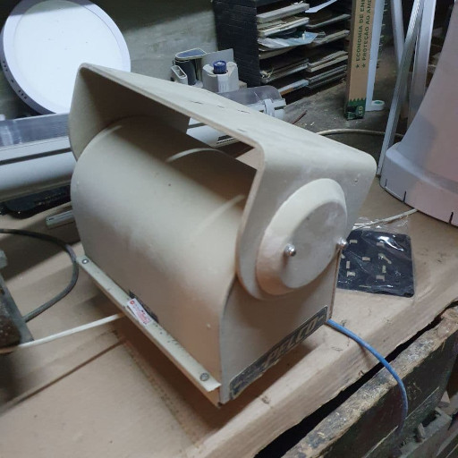
A few years ago I bought a Pelco Câmera Rotor, model PT175-24P. This rotor is made for carrying a camera with up to 8kg, and contains two biphase reversable motors internally. My idea was (and is) to put a satellite dish coupled, and control its movement to track satellites. Then I could use it to receive Low Orbit Satellites.
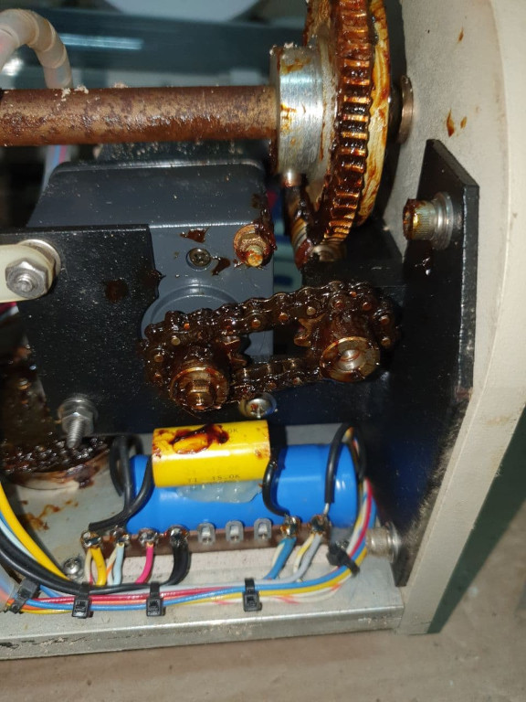
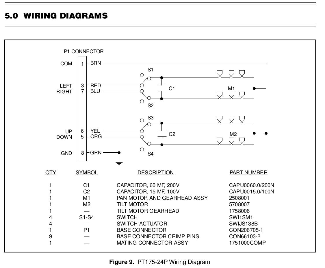 Internal Schematics
The problem of the original system from pelco, is that they’re two 24V AC Motors, which would require a VFD (Variable Frequency Driver) to control the speed and a closed-loop system with a angle sensor. That would make it a bit complex to control the antenna, so a friend of my (PY2UEP) suggested to modify it to use stepper motors instead. The big advantage of stepper motors is that their steps always has the same length. So if the motor goes N steps in one direction and then N steps in the oposite direction, it will return exactly where it started. That allows for open-loop circuits (where you just calibrate the start and then you dont need a feedback to fix everything).
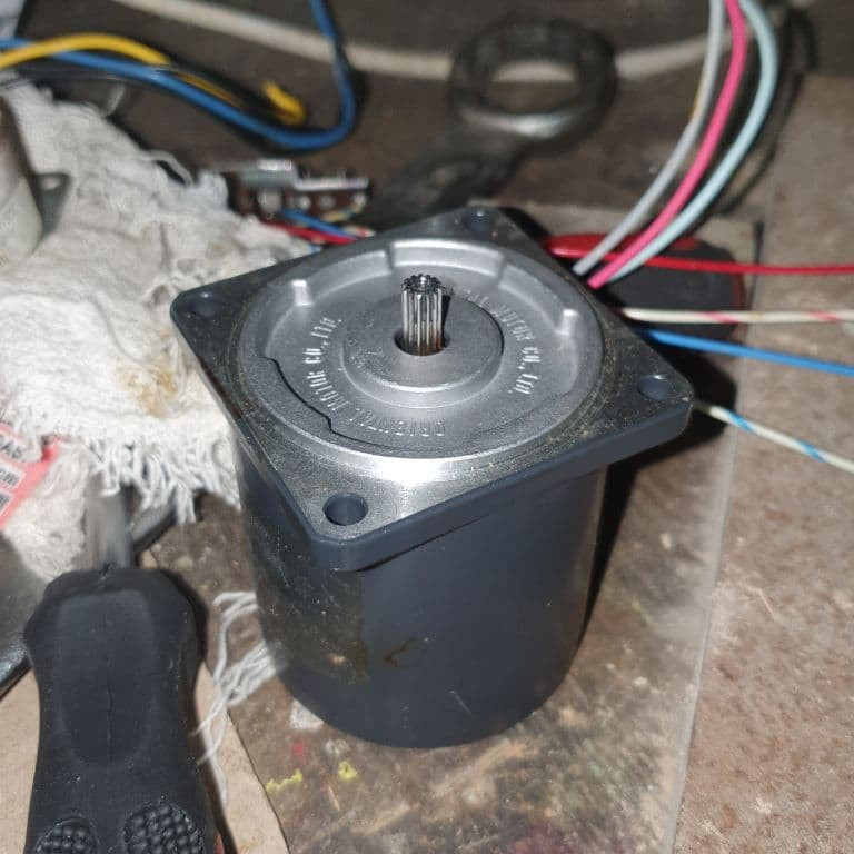
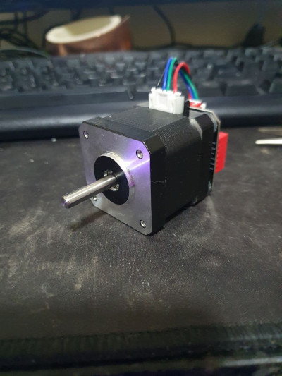 Stepper Motor
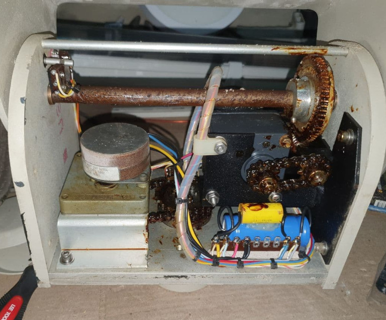
Make the cleaning
Then I started opening the rotor and make a super-clean. Remove all old grease and dust.
 Pelco Interior
 Pelco Interior
I disassembled everything and then made a querosene bath to remove grease from everywhere. Two of the azimuth rollers were well stuck (the grease was so dry that it looked like a glue), so I left in the querosene until the next day and then cleaned up with a paint brush. After all the cleaning, the rollers looks new!
The rest of the parts I basically tossed inside a bucket and filled with querosene with a bit of water. Then I started stiring the parts inside. After a while, I let it sit and made several washes with water and soap to remove all querosene.
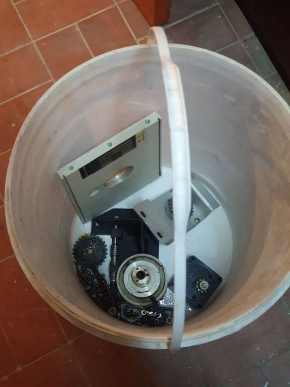 Bucket with washed parts
The belts I left on the querosene for a few minutes and then used a paint brush to remove all stuck pieces of grease.
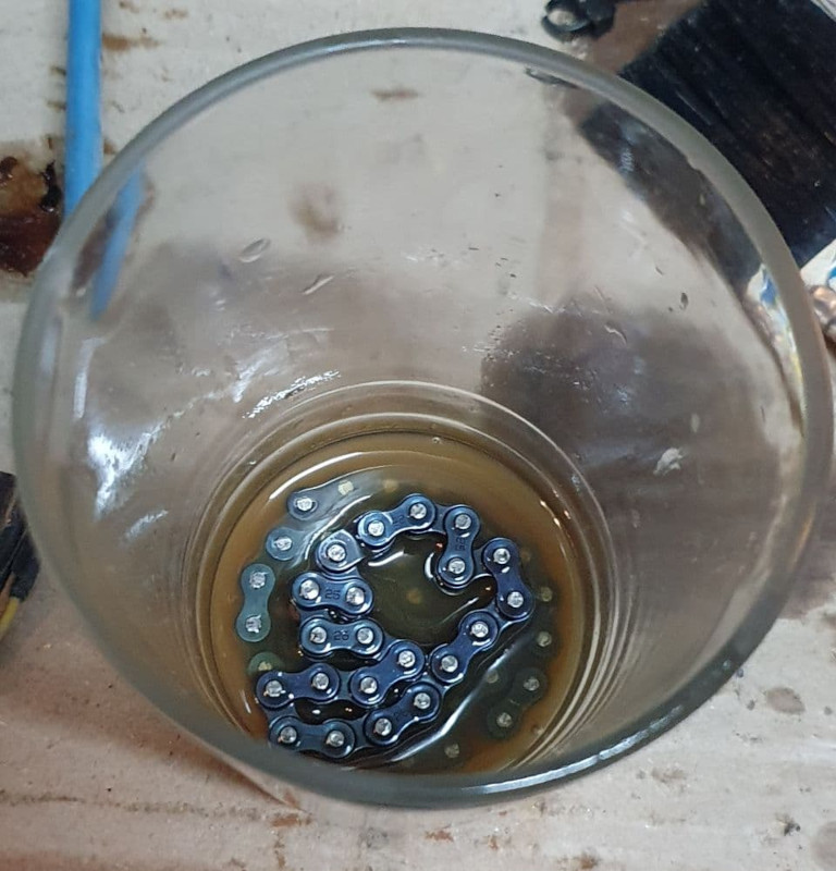 Belts in querosene
After all clean-up, I started the re-assembly by putting the two azimuth rollers in place. The one from below is stuck inside the piece under pressure, so I needed to use a hammer. With a lot of care, I managed to push the piece until it fit perfectly with the surface of the base. After that I pushed the azimuth axis through the roller.
Just after that, I put the reduction gears and the azimuth belt in place.
After that, everything was easy: just screw everything together. In the end I left it open so I could plan the position of the stepper motors:
 Open Pelco Mount
The next step is to disassemble the original motors and adapt the axis for the stepper motors!
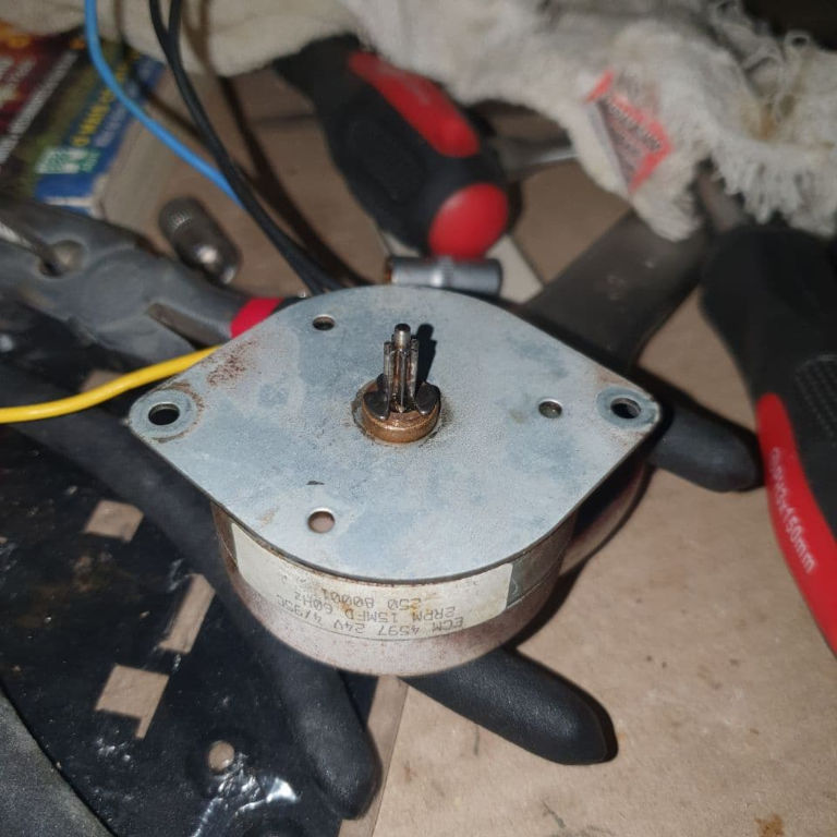 Azimuth Motor
 Elevation Motor
Cite this article Plain text · BibTeX
Suggested citation
Lucas Teske. “Antenna Rotor - Part 1.” Lets Hack It, 2021. https://lucasteske.dev/2021/03/rotor-antenna-parte-1.
BibTeX
@misc{teske2021rotorantennaparte1,
  author = {Lucas Teske},
  title = {Antenna Rotor - Part 1},
  year = {2021},
  publisher = {Lets Hack It},
  url = {https://lucasteske.dev/2021/03/rotor-antenna-parte-1}
}