Hacking Dimmer Touch Panel with ESP8266
 Written by
Lucas Teske
Written by
Lucas Teske
on
Hacking Dimmer Touch Panel with ESP8266
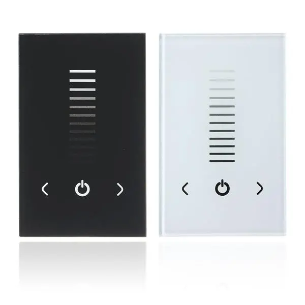
I bought two of these LED Touch Panel Dimmers in Banggood and they look pretty good. But since my house automation has its own way to controlling the lights I wonder if I could hack them to send info to Home Assistant.
The first thing I opened one of them to check what’s inside. It has two boards connected by a Flat Cable
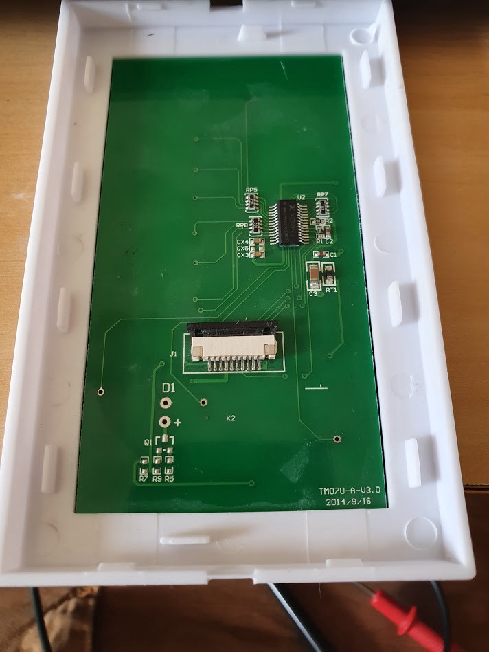 Touch Panel Board
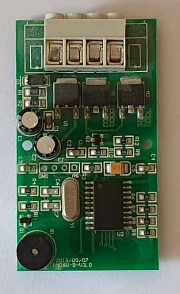 Dimmer Board
The dimmer board does have some micro controller that looks like a PIC, few mosfets and a buzzer. The touch panel has a WTC801SPI controller.
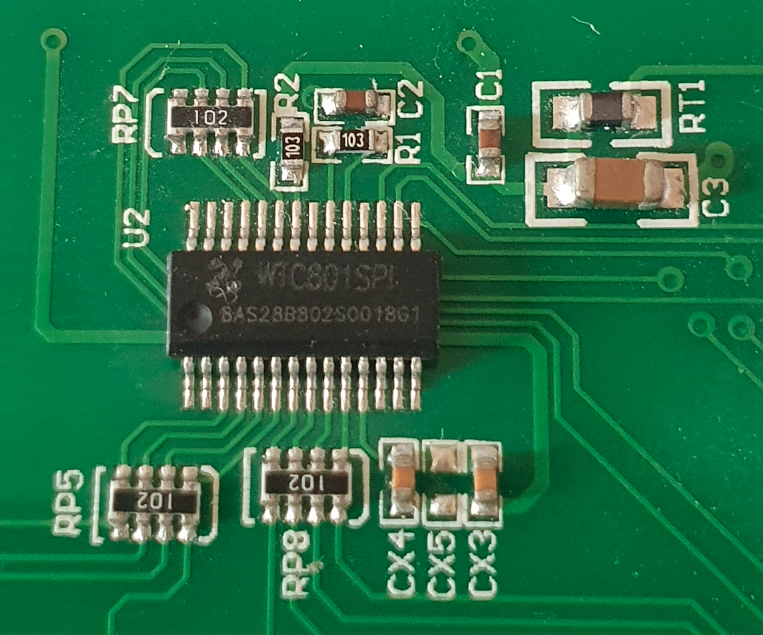 WTC801SPI Controller
Luckily the datasheet is available for this controller, and I was able to find the 10-pin flat cable connector pinout by using a multimeter and the datasheet info.
     1 -
     2 -
     3 - OUT_FLAG
     4 - GND
     5 -
     6 - CS
     7 - SCK
     8 - SI (Slave Input)
     9 - SO (Slave Output)
    10 - VCC
Some of the unmapped pins has some board connections which I will sometime map it (I think this board actually has a LED onboard). Still we got what we need: the SPI Data.
To test it, I got a small NodeMCU board (ESP8266) and hooked up like this:
     1 -
     2 -
     3 -
     4 - GND => ESP8266 GND
     5 -
     6 - CS  => ESP8266 GPIO15 (D8)
     7 - SCK => ESP8266 GPIO14 (D5)
     8 - SI  => ESP8266 GPIO13 (D7)
     9 - SO  => ESP8266 GPIO12 (D6)
    10 - VCC => ESP8266 3.3V
For now I ignored the OUT_FLAG pin, because I can just read it from the SPI bus. If I wanted to make a ultra low power setup, I could use this pin to wake up the ESP8266 from a deep sleep to process. The OUT_FLAG is high whenever any touch is made.
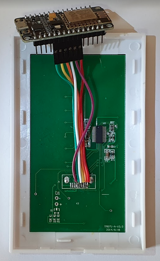 ESP8266 hooked to Touch Panel Board
Reading a bit more of the datasheet, this IC is pretty simple: You always read/write one byte and they always mean the same thing. No addresses, no commands, nothing. When you’re reading one byte it will report the state of one button or the slider:
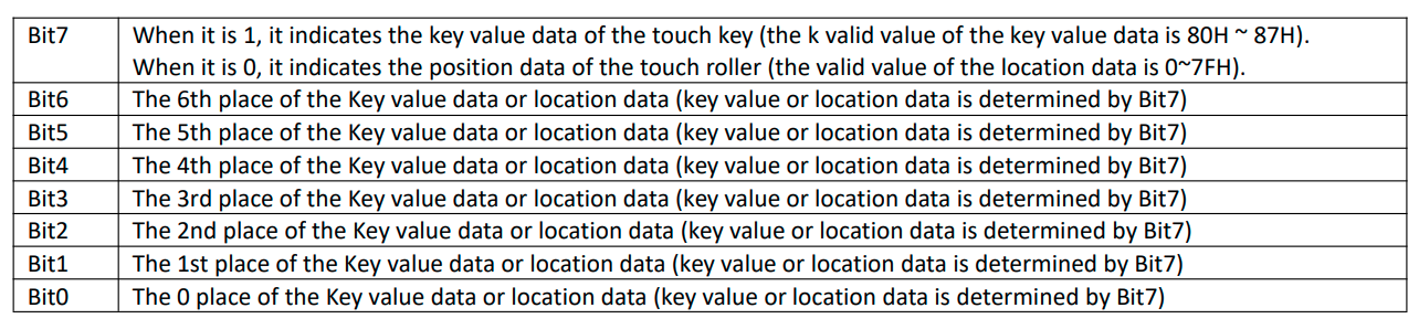 Bit map of read byte
So the 7th bit defines if the data you just read is a Slider value or Button Value. So I made a very simple sketch to get these values out:
#include <SPI.h>

#define SCK  D5
#define MISO D6
#define CS   D8
#define MOSI D7


void setup() {
  Serial.begin(115200);
  Serial.println("OK");

  pinMode(SCK, OUTPUT);
  pinMode(CS, OUTPUT);
  pinMode(MOSI, OUTPUT);
  pinMode(MISO, INPUT);

  digitalWrite(CS, HIGH);

  SPI.pins(SCK, MISO, MOSI, CS);
  SPI.begin();
}

void loop() {
  digitalWrite(CS, LOW);
  uint8_t data = SPI.transfer(0xFF); // Always transfer full 1 bits
  digitalWrite(CS, HIGH);

  Serial.println(data, BIN);
  delay(100);
}
What it does is: Keep the SI HIGH (by writing 0xFF) as the datasheet asks for, and read one byte from SO. Print as binary to the serial port and waits 100ms before trying again.
By running this and pressing some buttons, I can check that if nothing is pressed, it returns *11111111_.
Since the first bit tells us if its a button press or slider roll let’s make a different line printed for each:
#include <SPI.h>

#define SCK  D5
#define MISO D6
#define CS   D8
#define MOSI D7


void setup() {
  Serial.begin(115200);
  Serial.println("OK");

  pinMode(SCK, OUTPUT);
  pinMode(CS, OUTPUT);
  pinMode(MOSI, OUTPUT);
  pinMode(MISO, INPUT);

  digitalWrite(CS, HIGH);

  SPI.pins(SCK, MISO, MOSI, CS);
  SPI.begin();
}

void loop() {
  digitalWrite(CS, LOW);
  uint8_t data = SPI.transfer(0xFF); // Always transfer full 1 bits
  digitalWrite(CS, HIGH);

  uint8_t flag = data & 0x80; // Get the 7th bit
  data &= 0x7F; // Reset it, so we have only the pure value in data

  if (flag) { // Buttons
    Serial.print("BUTTONS: ");
    Serial.println(data, BIN);
  } else {    // Slider
    Serial.print("SLIDER: ");
    Serial.println(data, DEC);
  }
  delay(100);
}
Since the roller should give us a number, it will now print as decimal. The buttons will still be printed as binary.
Then by testing the slider, I noticed the range is from 1 to 54 (54 being the bottom and 1 being top. Which by the drawings should be 100% to 54 and 0% to 1). As for the buttons:
- 0b => When Right button is pressed
- 1b => When Power button is pressed
- 10b => When Left button is pressed
Pressing more than one button at same time doesn’t make any effect. The IC just keeps the first pressed button down. By the binary numbers we can expect the data variable to be:
- 0 => When Right button is pressed
- 1 => When Power button is pressed
- 2 => When Left button is pressed
- 127 => When none are pressed (all 1’s)
With that information we can do a better parsing of everything:
#include <SPI.h>

#define SCK  D5
#define MISO D6
#define CS   D8
#define MOSI D7


void setup() {
  Serial.begin(115200);
  Serial.println("OK");

  pinMode(SCK, OUTPUT);
  pinMode(CS, OUTPUT);
  pinMode(MOSI, OUTPUT);
  pinMode(MISO, INPUT);

  digitalWrite(CS, HIGH);

  SPI.pins(SCK, MISO, MOSI, CS);
  SPI.begin();
}

void loop() {
  digitalWrite(CS, LOW);
  uint8_t data = SPI.transfer(0xFF); // Always transfer full 1 bits
  digitalWrite(CS, HIGH);

  uint8_t flag = data & 0x80; // Get the 7th bit
  data &= 0x7F; // Reset it, so we have only the pure value in data

  if (data != 0x7F) {
    // We have some data, not all 1's
    if (flag) { // Buttons
      Serial.print("BUTTONS: ");
      switch (data) {
        case 0:
          Serial.println("RIGHT");
          break
        case 1:
          Serial.println("POWER");
          break
        case 2:
          Serial.println("LEFT");
          break
      }
    } else {    // Slider
      Serial.print("SLIDER: ");
      // MAX is 54 and MIN is 1 so:
      uint16_t v = (uint16_t)data;
      v -= 1;   // MIN
      v *= 100; // Percent
      v /= (54 - 1);  // MAX - MIN
      Serial.print(v);
      Serial.println("%");
    }
  }
  delay(100);
}
Now we have the slider information in percent and button presses by name. There are some more nice work you can do, but I did a small library that does everything for you in a event way: https://github.com/racerxdl/wtc801
This hack was pretty simple, but I want to write about it. Sometime later I will write about the Home Assistant integration. Hope you like it!