NAND Flash Memory Analysis and Decoding - Unveiling ECC Scattering in Unknown Devices
 Written by
Lucas Teske
Written by
Lucas Teske
on
Exploring NAND Memories
When in possession of a device whose internals one wishes to understand, accessing the content of the flash memory is not always straightforward. Due to the nature of NAND memories, an error correction algorithm is applied to all content, which can cause unintentional obfuscation of the content. Some manufacturers of processors that directly control NAND-type memories or developers of “protected” software choose to customize the way these algorithms function.
In this article, we will explore the basic structure of flash memory, why error correction exists, and how to identify the scattering of the error correction algorithm used.
Flash Memories
Flash memories have emerged as the backbone of digital storage in the contemporary era. Found in devices as varied as SSDs, USB drives, and SD cards, these memories bring an irresistible combination of speed, durability, and the ability to retain data even in the absence of power.
Historically, before the rise of flash memories, the main storage devices were based on magnetic media, such as hard disks and floppy disks, or on EPROMs (Erasable Programmable Read-Only Memory). While magnetic media had moving parts and were more prone to physical failures, EPROMs required a specific erasure process, making the rewriting of data a slower and less efficient process.
Within the category of flash memories, we find different variations, with NOR and NAND versions being the most predominant. In this article, we will focus on NAND flash memories, recognized for their high storage density and widely used in everyday storage devices, ensuring speed and reliability in reading and writing data.
Anatomy of a NAND Cell
 Detailed diagram of a NAND cell
At the heart of flash memory technology lies the intricate architecture of a NAND cell. The illustration above outlines the fundamental components of the cell: the Control Gate, the Floating Gate, insulating oxide layers, along with N-Type Source and N-Type Drain terminals, all built on a P-type substrate. Bits are stored in the flash memory by retaining electrons in the Floating Gate.
During the write operation, a voltage is imposed on the Control Gate, inducing electrons to cross the oxide barrier and lodge in the Floating Gate. Once the electrons reach the Floating Gate, they remain there, denoting a “written” state.

To read the stored information, a voltage is applied to the Control Gate. If there are electrons in the Floating Gate, they will create a repulsive force, blocking the flow of electrons from the Source to the Drain. This state is recognized as a “0” bit. However, if the Floating Gate is unoccupied, the electric current will flow unimpeded, corresponding to a “1” bit.
NAND cell in the “written” state
Finally, the electronic configuration — whether its absence or presence — determines whether the cell is representing a “0” or “1” bit. The subsequent image shows a cell in the “erased” state, characterized by the free flow of electrons between the terminals.
 NAND cell in the “erased” state
NAND Memory Architecture
 Diagram representing the organization of a NAND block
NAND memory is meticulously organized in a hierarchical structure. Starting with the smallest unit, we have the cell. These cells are grouped to form pages. Moving up the hierarchy, multiple pages are then consolidated to constitute a block, as illustrated in the diagram above.
This structural arrangement is not just for organization. It plays a vital role in the efficiency of flash memory operations. An important detail to consider is that, in various devices based on flash technology, the erase operation is performed at the block level, and not on individual cells or pages.
The image exemplifies a NAND memory containing pages of 2048 bytes of data added with 64 bytes designated for error correction, totaling 2112 bytes per page. These pages are grouped into blocks that house 64 pages each, resulting in 128K bytes of data and 4K bytes for correction.
The additional bytes in each page are not mere supplements. They are intrinsic to the memory’s integrity. Although stored in the same way as any other byte, they are often allocated for specific functions, such as parity in Error Correction (ECC) algorithms. This correction is indispensable, as during manufacturing or even over use, some cells of the NAND memory may present defects or wear out, compromising the accuracy of stored data. Therefore, ECC acts as a protective layer, ensuring the reliability of data even in the presence of imperfections in the memory.
Reading Flash Memories
When dealing with reading and writing in Flash memories, a variety of devices are available. For flash memories with less conventional encapsulations, like BGA (Ball Grid Array), I often turn to the RT809H programmer, using a specific adapter for such encapsulation. The flash memory in question was originally extracted from a device by PAX, a model available on Mercado Livre under the description “card machine”. It is worth mentioning that the encapsulation type of this flash memory is BGA63, indicating an arrangement of 63 pins in the ball-grid-array format.
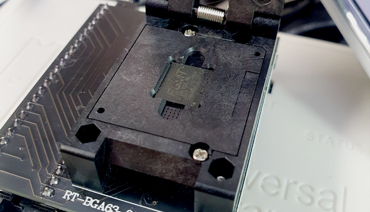 Flash Memory in the universal programmer RT809H ready for reading
After extracting the data from the flash memory, a crucial step is using the binwalk tool. This command functions to scan and list possible signatures of known files contained in the memory dump, allowing a preliminary analysis of its content. This stage is essential to discern if we will face challenges when trying to decipher the stored data, such as if they are encrypted.
It is important to note that the image produced by the RT809H programmer depicts the content of the flash memory in its purest state, without any filtering. This means that the ECC (Error-Correcting Code) parity bits are included. This feature can introduce nuances during the analysis, as not all signatures will be accurately recognized, especially considering files that may start at the end of a memory page.
$ binwalk F59L1G81MA@BGA63_1111.BIN

DECIMAL       HEXADECIMAL     DESCRIPTION
--------------------------------------------------------------------------------
438548        0x6B114         Base64 standard index table
(...)
3514378       0x35A00A        PC bitmap, Windows 3.x format,, 320 x 240 x 24
7839754       0x77A00A        uImage header, header size: 64 bytes, header CRC: 0x538F3DE9, created: 2021-05-27 08:14:51, image size: 3696472 bytes, Data Address: 0x80800000, Entry Point: 0x80800000, data CRC: 0xA22F74A5, OS: Linux, CPU: ARM, image type: OS Kernel Image, compression type: none, image name: "Linux-2.7.93.9707R"
7839818       0x77A04A        Linux kernel ARM boot executable zImage (little-endian)
7857081       0x77E3B9        gzip compressed data, maximum compression, from Unix, last modified: 1970-01-01 00:00:00 (null date)
(...)
20815882      0x13DA00A       uImage header, header size: 64 bytes, header CRC: 0xF95F6882, created: 2021-05-27 08:20:25, image size: 8185419 bytes, Data Address: 0x83800000, Entry Point: 0x83800000, data CRC: 0xE5674944, OS: Linux, CPU: ARM, image type: RAMDisk Image, compression type: none, image name: "RAMDISK-2.7.93.9707R"
(...)
20815946      0x13DA04A       gzip compressed data, maximum compression, from Unix, last modified: 2021-05-27 08:20:23
33792010      0x203A00A       uImage header, header size: 64 bytes, header CRC: 0x588DFFBC, created: 2021-05-27 08:19:13, image size: 6412038 bytes, Data Address: 0x0, Entry Point: 0x0, data CRC: 0x32979F1E, OS: Linux, CPU: ARM, image type: Firmware Image, compression type: none, image name: "BASE-2.7.93.9707R"
33792074      0x203A04A       gzip compressed data, maximum compression, from Unix, last modified: 2021-05-27 08:19:11
46768138      0x2C9A00A       UBI erase count header, version: 1, EC: 0x3, VID header offset: 0x800, data offset: 0x1000
Entropy assessment is an effective technique to detect encrypted or compressed content in a memory. When we talk about entropy in data, we are referring to the amount of information or unpredictability contained in these data. The binwalk tool offers a specific mode for measuring this entropy.
Files that are compressed or encrypted tend to display an apparently random data pattern, resulting in an entropy measure that approaches 1. In contrast, “plain-text” files or unencoded data generally have significantly lower entropy, tending towards values closer to 0, as their content is more predictable.
To explore this functionality in binwalk, use the -E option, which activates the entropy measurement mode. When executed, you will receive a graph that visually represents the entropy variations throughout the file, facilitating the identification of encrypted or compressed segments.
$ binwalk -E F59L1G81MA@BGA63_1111.BIN
DECIMAL       HEXADECIMAL     ENTROPY
--------------------------------------------------------------------------------
0             0x0             Falling entropy edge (0.027839)
7880704       0x784000        Rising entropy edge (0.995063)
12345344      0xBC6000        Falling entropy edge (0.000000)
20869120      0x13E7000       Rising entropy edge (0.997811)
29257728      0x1BE7000       Falling entropy edge (0.000000)
33824768      0x2042000       Rising entropy edge (0.999076)
40386560      0x2684000       Falling entropy edge (0.372003)
47253504      0x2D10800       Falling entropy edge (0.725862)
62879744      0x3BF7800       Falling entropy edge (0.737729)
67244032      0x4021000       Rising entropy edge (0.966013)
67311616      0x4031800       Falling entropy edge (0.776734)
69611520      0x4263000       Falling entropy edge (0.790624)
69679104      0x4273800       Rising entropy edge (0.972091)
69814272      0x4294800       Falling entropy edge (0.836573)
70322176      0x4310800       Falling entropy edge (0.844177)
72689664      0x4552800       Falling entropy edge (0.643195)
74008576      0x4694800       Falling entropy edge (0.783870)
74584064      0x4721000       Falling entropy edge (0.471472)
75259904      0x47C6000       Falling entropy edge (0.787818)
76613632      0x4910800       Falling entropy edge (0.823394)
76748800      0x4931800       Falling entropy edge (0.687502)
82837504      0x4F00000       Falling entropy edge (0.360502)
84291584      0x5063000       Falling entropy edge (0.775172)
84934656      0x5100000       Falling entropy edge (0.714603)
95385600      0x5AF7800       Falling entropy edge (0.788762)
103233536     0x6273800       Falling entropy edge (0.775540)
104992768     0x6421000       Falling entropy edge (0.750242)
124475392     0x76B5800       Falling entropy edge (0.281623)
125253632     0x7773800       Falling entropy edge (0.750710)
133507072     0x7F52800       Falling entropy edge (0.798972)
137566208     0x8331800       Falling entropy edge (0.768062)
137701376     0x8352800       Falling entropy edge (0.743758)
 Entropy of the Read Image
In the presented entropy graph, the areas of high entropy stand out as peaks that approach the value of 1 on the vertical axis. These regions point to sections of data that have a distribution of bits that appears random, which is typical of compressed or encrypted data.
By correlating the position of these peaks with the information provided by the binwalk command, we can understand the nature of these high entropy segments. In our case, the points of high entropy correspond to compressed parts, and not encrypted data. This deduction becomes clear when we see that binwalk identified signatures related to data compressed with gzip at the indicated positions.
The fact of recognizing these signatures clearly shows that the content, although compressed, is not encrypted. If it were, binwalk would not have identified these signatures, as encrypted data looks like a bunch of random information, without specific patterns. Thus, looking at both the entropy graph and the information from binwalk, we get a good idea of the structure and type of data in the analyzed flash memory.
When ECC Scattering is Not Standard
To ensure that data is accessed accurately, it is crucial to exclude the parity bits inserted into each memory page. Assuming that the last 64 bytes of each page are allocated for ECC, we can create a Python script that reads the 2112 bytes (representing the full memory page) and writes only the 2048 bytes corresponding to the pure data, disregarding the ECC, into a new file.
#!/usr/bin/env python

f = open("F59L1G81MA@BGA63_1111.BIN", "rb")
o = open("FIXEDDATA.bin", "wb")
pagesToRead = 65536
for i in range(pagesToRead):
  page = f.read(2112)
  data = bytearray(page[:2048]) # Nuke ECC
  o.write(data)

f.close()
o.close()
With the data now cleaned, the next step is to identify the files present to verify the efficacy of our assumption. A quick look at the list of files highlighted by binwalk will give us an indication.
$ binwalk F59L1G81MA@BGA63_1111.BIN

DECIMAL       HEXADECIMAL     DESCRIPTION
--------------------------------------------------------------------------------
438548        0x6B114         Base64 standard index table
439650        0x6B562         DES PC1 table
439738        0x6B5BA         DES PC2 table
440945        0x6BA71         DES SP2, little endian
441738        0x6BD8A         DES SP1, little endian
477666        0x749E2         Certificate in DER format (x509 v3), header (...)
478540        0x74D4C         Object signature in DER format (PKCS header (...)
479065        0x74F59         Object signature in DER format (PKCS header (...)
1384724       0x152114        Base64 standard index table
1385826       0x152562        DES PC1 table
1385914       0x1525BA        DES PC2 table
1387121       0x152A71        DES SP2, little endian
1387914       0x152D8A        DES SP1, little endian
1423842       0x15B9E2        Certificate in DER format (x509 v3), header (...)
1424716       0x15BD4C        Object signature in DER format (PKCS header (...)
1425241       0x15BF59        Object signature in DER format (PKCS header (...)
3514378       0x35A00A        PC bitmap, Windows 3.x format,, 320 x 240 x 24
7839754       0x77A00A        uImage header, header size: 64 bytes, header (...)
7839818       0x77A04A        Linux kernel ARM boot executable zImage (litt(...)
7857081       0x77E3B9        gzip compressed data, maximum compression,   (...)
(...)
We can identify a bitmap right at the beginning of the image, where binwalk is even able to identify its size and bit depth:
3514378 0x35A00A PC bitmap, Windows 3.x format,, 320 x 240 x 24
A distinctive characteristic of bitmaps is the way they store color information. The bytes in the file map directly to the colors of the image. Thus, when we have a region of the image that displays a single color, that color is represented by consecutive sequences of identical bytes in the file. This property is especially useful when we try to discern the distribution of error-correcting bits (ECC). If a segment of the bitmap, fitting to a memory page, displays the same color as another segment on a different page, it’s expected that their corresponding ECC bits would be identical.
Considering that the identified image has a color depth of 24 bpp (bits per pixel), each pixel is represented by 3 bytes. Given a memory page capacity of 2048 bytes, this translates to about 682 pixels per page. This is slightly more than two lines of the image. The attempt to access the bitmap in its current form suggests inconsistencies, leading us to question our initial assumptions about the distribution of ECC bits.
 Corrupted PAX Logo
For proper interpretation, it’s vital to extract multiple pages from the memory containing the bitmap data in an aligned manner. This way, we can ensure that at every 2112 byte interval, we are dealing with a new page, not a continuation of the previous one. Subsequently, we can use an image editing software that allows manipulating images in arbitrary “RAW” formats. In this context, we will use GIMP to analyze the raw image data. One of the advantages of GIMP is the flexibility in defining the image geometry and pixel formatting.
To facilitate the identification of ECC bits, we’ll set the image width to 2112, corresponding to the memory page size. This will allow us to visualize each memory page as a distinct line. We’ll choose an 8-bit per pixel representation in monochrome to ensure an exact correspondence of 2112 bytes per line. Regarding the height, we’ll opt for at least 100 lines to provide a clear view of variations between different memory pages.
Examining the visual representation provided by GIMP, we notice clearly defined segments of 512 bytes within each memory page. These segments are interspersed with thinner columns, whose appearance seems directly influenced by the adjacent block.
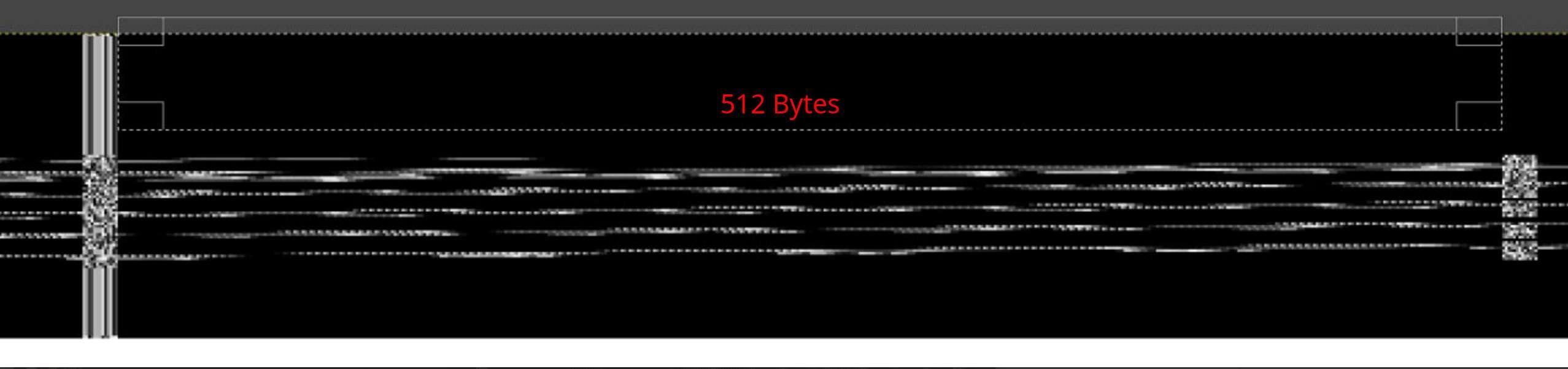 512 byte blocks
Looking closer, we realize that the completely black lines display a column with consistent patterns to the left of the 512-byte mark. Contrary to this, lines that show some variation also manifest discrepancies in that same column on the left. Based on this observation, we can infer that the columns positioned both to the left and right of the 512-byte segment represent parity data, and are not an intrinsic part of the bitmap. This becomes even more evident considering that the first lines of the bitmap are entirely black.
Considering the memory page as a whole, another detail stands out: despite the observed pattern, there is a completely white column in an unexpected position. Additionally, the first column, which theoretically should be white, appears to be displaced or altered in some way.
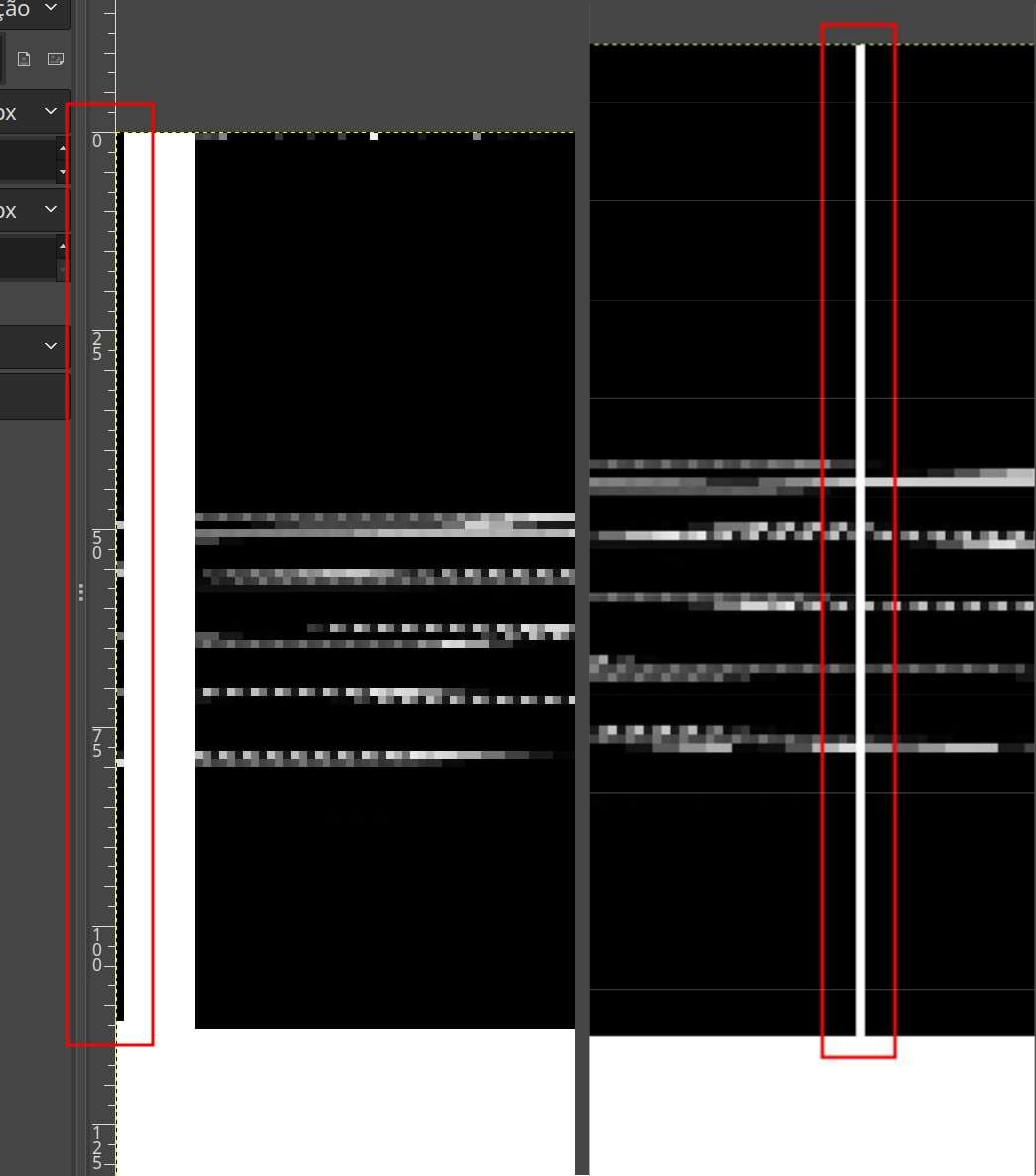 Column apparently switched place
The hypothesis suggests that, for some reason, these columns may have been switched during the scattering process. To validate this assumption, a practical approach would be to use GIMP itself to reposition the column and assess if the resulting content aligns harmoniously with the rest of the memory page.
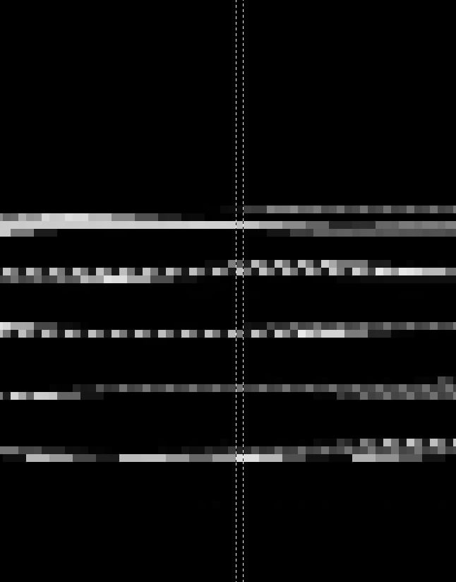 Switching identified columns
The above image validates our conjecture, highlighting that the reallocation of columns provides a more coherent visualization of the content. Although it seems unusual at first glance, considering the security nature of the device, it is plausible to think that this altered arrangement could be a deliberate way of hiding data. This peculiarity is not mentioned in any public documentation available for the device’s processor.
Based on these findings, we have the tools needed to refine our Python script, aiming to eliminate the parity bits and rearrange the 512-byte segments, in order to obtain a refined and coherent image.
#!/usr/bin/env python

f = open("F59L1G81MA@BGA63_1111.BIN", "rb")
o = open("FIXEDDATA.bin", "wb")
pagesToRead = 65536
for i in range(pagesToRead):
  page = f.read(2112)
  data = bytearray(page[10:10+512] + page[535:535+512] + page[1060:1060+512] + page[1585:1585+512])
  data[len(data)-48-1] = page[0]
  o.write(data)

f.close()
o.close()
After all the steps of analysis and correction, we successfully extracted the bitmap and validated that all our hypotheses and methods of analysis were correct:
 Adjusted PAX Logo
Conclusion
It is essential to highlight that our approach was limited to removing the parity bits, without actually applying the error correction algorithm. As mentioned earlier, flash memories, particularly NAND type, can have defective bits, even from the time of manufacturing. Omitting the specific ECC algorithm may result in inconsistencies in the final data.
Fortunately, the content of this specific device was not encrypted, which made it easier for us in the analysis of scattering, taking advantage only of known content. If the content had been encrypted, it would be essential to identify a recurring pattern (such as empty memory pages) where the ECC information would be recorded.
Cite this article Plain text · BibTeX
Suggested citation
Lucas Teske. “NAND Flash Memory Analysis and Decoding - Unveiling ECC Scattering in Unknown Devices.” Lets Hack It, 2024. https://lucasteske.dev/2024/01/decoding-and-analysis-nand-flash.
BibTeX
@misc{teske2024decodingandanalysisnandflash,
  author = {Lucas Teske},
  title = {NAND Flash Memory Analysis and Decoding - Unveiling ECC Scattering in Unknown Devices},
  year = {2024},
  publisher = {Lets Hack It},
  url = {https://lucasteske.dev/2024/01/decoding-and-analysis-nand-flash}
}