Hacking a ESP32 into FPGA Board
 Written by
Lucas Teske
Written by
Lucas Teske
on
Hacking a ESP32 into FPGA Board
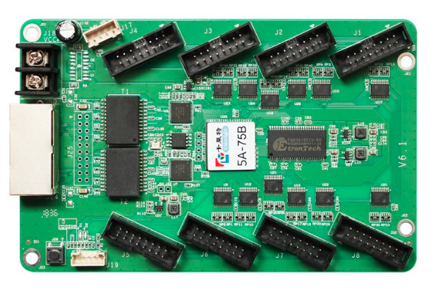
Colorlight Hub 5A-75B V6.1 Board
Last year I saw a russian guy that found out that this cheap board (US$15~) had an Lattice ECP5 FPGA, which is compatible with Open Source Tool-chains for synthesis. He was running a RISC-V Core inside that and piping the serial through the ethernet ports. I wanted to get one and start playing by myself. These boards are relatively cheap, about US$15 and contains a Lattice ECP5 FPGA ( LFE5U-25F-6BG381C ), 4MB DRAM, Two Gigabit Ethernet and several level shifters for I/O. This is good because:
- That’s a very cheap board by the specs
- You can use open-source synth toolchain
- There is lots of 5V bi-directional level shifters
I decided to give a shot and buy one from Aliexpress. Sadly because of the pandemic COVID-19, the package is long time delayed (still haven’t arrived yet, 3 months after I bought). Luckily I found it on Mercado Livre (the Brazilian eBay) to sell at a reasonable price.
When it arrived, I first tried to run the classic Hardware Hello World: The led blink. For that I got this project to test it: https://github.com/antonblanchard/ghdl-yosys-blink
I did a fork to add the board constraints, and also a FT232R bitbang mode to OpenOCD (since it was the only JTAG adapter I had at the moment)[ see https://github.com/racerxdl/ghdl-yosys-blink ]
I didn’t have to reverse engineer the board, since someone already did all the reverse engineering: https://github.com/q3k/chubby75/blob/master/5a-75b/hardware_V6.1.md
The JTAG Headers are easy to access, and all pinouts are mapped. Great!
After few minutes tuning the ghdl-yosis-blink example I managed to make it work on my board. Still it was running on ram memory only and I wanted to write to SPI Flash. Lattice allows to write the SPI Flash using the jtag, so I started searching over the internet stuff that could convert the generated bitstream to program the flash. After testing lots of tools, I found out this simple tool did the job: https://github.com/f32c/tools/tree/master/ujprog
I just had to run:
ujprog -d -j flash -s vhdl_blink-flash.svf vhdl_blink.bit
And the generated vhdl_blink-flash.svf was persisting into the flash memory.
After few days I managed to write thr SPI Flash using FT232H. Full #opensource stuff to program that board. Also only US$15. pic.twitter.com/RujsOGwH1D
— Cybernetic Lover (@lucasteske) June 4, 2020
Now that everything was working, I decided to make a bigger hack: I wanted an ESP32 to be attached in the board and program through network. It would also be nice if I could redirect a serial port to the network (useful for debug).
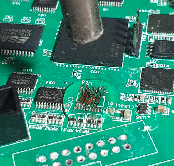
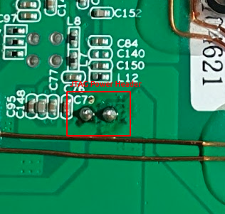
The first thing I did is chose a GPIO pair to be the TX/RX from the serial port. The ESP32 has three serial ports, but on my board only two of them were exposed (Serial 0 and 2). The Serial 0 port is attached to the USB-Serial converter onboard, so I decided to use the Serial 2 to communicate with the FPGA. After looking at the pinout, most of the Level Shifters pins are common (the address lines are half of the pins) and the ones close to the lower part of the board (which would be easier to solder) were the address lines. After poking around, I decided to remove the J4 connector and U23 level shifter (the ESP32 is 3.3V, remember that!)
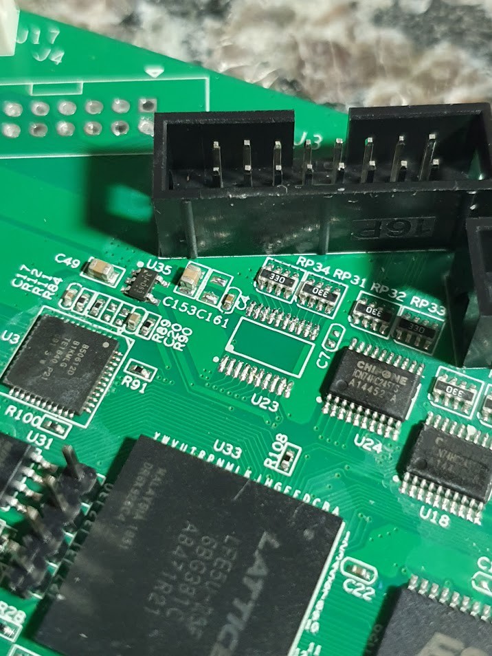 U23 and J4 removed
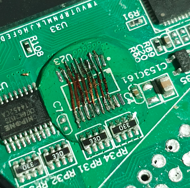
I also decided to remove J3 to make easier to solder the bypass wires at that connector. Then I soldered all bypass wires to make it 3.3V instead 5V
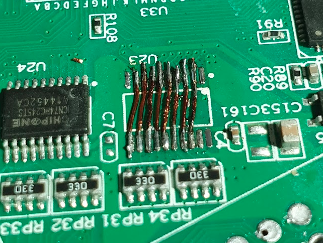 Bypass wires soldered in U23
The 33 Ohm resistors are nice since it could avoid short circuits when wrong pins are associated to serial port. So I decided to keep them as is. After checking that all pins were OK and not shorted, I decided to use hot-glue to secure them:
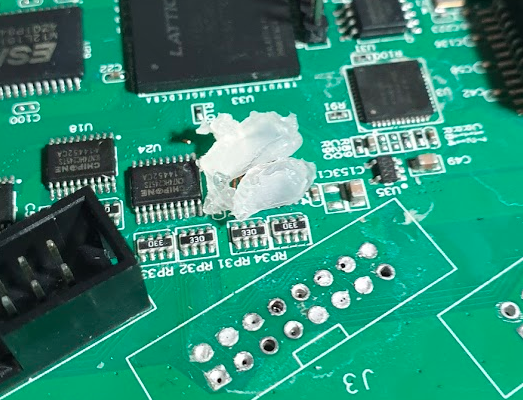 Hot-glue raw pieces
I always found out that using a heat-gun with 200ºC was better to hot-glue than the hot-glue gun. Also I would avoid heating the wires too much and letting them go.
 Heat gun with hot-glue
After cooling down, the results look really good:
 Hot-glue on bypass wires
Then I went to the back-side of the board to solder the VCC/GND pair and the TX/RX pair wires. Luckily the power input for this board is 3.6 to 6V and then I can use the VIN from ESP32 (which is attached to USB +5V) to power it. The power connector is also close to J4 we removed.
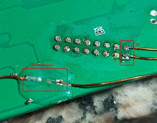 Power Connector and Serial Port
Then with some double-sided tape, I could attach the ESP32 to the side of the board and solder the wires to the right pins.
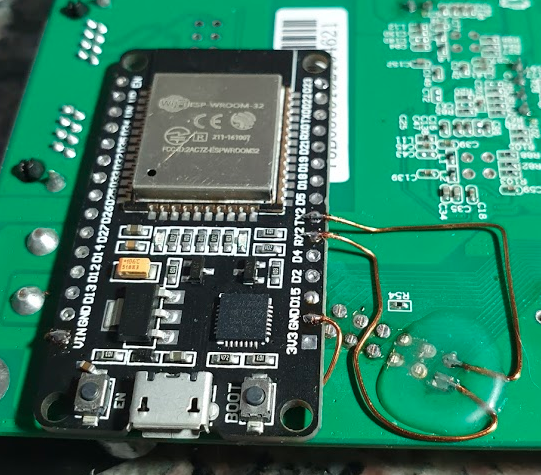 ESP32 fixed with double-sided table and wires soldered
Now I just had to choose some pins for the JTAG and we would be good to go! After searching for some safe pins on ESP32 I choose these:
- TDI => D33
- TDO => D32
- TCK => D27
- TMS => D26
And I soldered the wires as best looking as I could.

I also had to solder the GND of the ESP32 into the GND of the JTAG header (I had a problem the FT232R that was solved by attaching the GND to the header there)
 JTAG Power Header
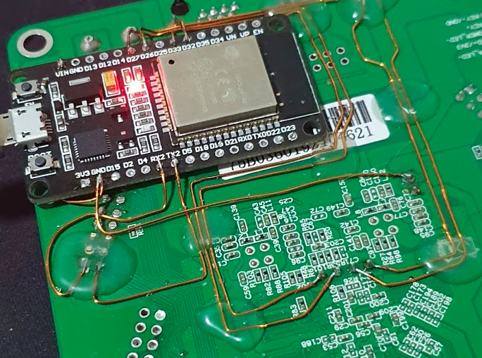 GND wire soldered
With all wires soldered, I could start playing with software!
At first I tried the OpenOCD Remote Bitbang which connects to TCP socket and start issuing bitbang commands by using a single ASCII character. For some reason I couldn’t make it work right. If you want to try by yourself:
#include <WiFi.h>

const char* ssid     = "XX";
const char* password = "XX";

WiFiServer server(3335);

#define PIN_SRST 21
#define PIN_TDI 33
#define PIN_TDO 32
#define PIN_TCK 27
#define PIN_TMS 26
#define PIN_LED 2

void setup() {
    Serial.begin(115200);
    delay(10);

    pinMode(PIN_SRST, OUTPUT);
    pinMode(PIN_TDI, OUTPUT);
    pinMode(PIN_TDO, INPUT_PULLUP);
    pinMode(PIN_TCK, OUTPUT);
    pinMode(PIN_TMS, OUTPUT);
    pinMode(PIN_LED, OUTPUT);
    digitalWrite(PIN_SRST, HIGH);
    digitalWrite(PIN_TDI, HIGH);
    digitalWrite(PIN_TCK, LOW);
    digitalWrite(PIN_TMS, HIGH);
    digitalWrite(PIN_LED, HIGH);
    // We start by connecting to a WiFi network

    Serial.println();
    Serial.println();
    Serial.print("Connecting to ");
    Serial.println(ssid);

    WiFi.begin(ssid, password);

    while (WiFi.status() != WL_CONNECTED) {
        delay(500);
        Serial.print(".");
    }

    Serial.println("");
    Serial.println("WiFi connected.");
    Serial.println("IP address: ");
    Serial.println(WiFi.localIP());
    server.begin();
}

void loop() {
    WiFiClient client = server.available();
    if (client) {                     // if you get a client,
        Serial.println("New Client.");  // print a message out the serial port
        while (client.connected()) {
            if (client.available()) {
                char c = client.read();
                switch (c) {
                    case 'B':
                      digitalWrite(PIN_LED, HIGH);
                      break;
                    case 'b':
                      digitalWrite(PIN_LED, LOW);
                      break;
                    case 'R':
                      client.print((digitalRead(PIN_TDO) == HIGH) ? '1' : '0');
                      break;
                    case 'Q':
                      break;
                    case '0':
                      digitalWrite(PIN_TMS, LOW);
                      digitalWrite(PIN_TDI, LOW);
                      digitalWrite(PIN_LED, LOW);
                      digitalWrite(PIN_TCK, LOW);
                      break;
                    case '1':
                      digitalWrite(PIN_TMS, LOW);
                      digitalWrite(PIN_TDI, HIGH);
                      digitalWrite(PIN_LED, LOW);
                      digitalWrite(PIN_TCK, LOW);
                      break;
                    case '2':
                      digitalWrite(PIN_TMS, HIGH);
                      digitalWrite(PIN_TDI, LOW);
                      digitalWrite(PIN_LED, LOW);
                      digitalWrite(PIN_TCK, LOW);
                      break;
                    case '3':
                      digitalWrite(PIN_TMS, HIGH);
                      digitalWrite(PIN_TDI, HIGH);
                      digitalWrite(PIN_LED, LOW);
                      digitalWrite(PIN_TCK, LOW);
                      break;
                    case '4':
                      digitalWrite(PIN_TMS, LOW);
                      digitalWrite(PIN_TDI, LOW);
                      digitalWrite(PIN_LED, HIGH);
                      digitalWrite(PIN_TCK, HIGH);
                      break;
                    case '5':
                      digitalWrite(PIN_TMS, LOW);
                      digitalWrite(PIN_TDI, HIGH);
                      digitalWrite(PIN_LED, HIGH);
                      digitalWrite(PIN_TCK, HIGH);
                      break;
                    case '6':
                      digitalWrite(PIN_TMS, HIGH);
                      digitalWrite(PIN_TDI, LOW);
                      digitalWrite(PIN_LED, HIGH);
                      digitalWrite(PIN_TCK, HIGH);
                      break;
                    case '7':
                      digitalWrite(PIN_TMS, HIGH);
                      digitalWrite(PIN_TDI, HIGH);
                      digitalWrite(PIN_LED, HIGH);
                      digitalWrite(PIN_TCK, HIGH);
                      break;
                    case 'r':
                    case 't':
                      // SRST=0, which confusingly means to *exit* reset (as /RESET and /TRST are active-low)
                      // We don't have a TRST connection, so 'r' and 't' do the same thing.
                      digitalWrite(PIN_SRST, HIGH);
                      //digitalWrite(PIN_CHIP_EN, HIGH);
                      break;
                    case 's':
                    case 'u':
                      // SRST=1 -- enter RESET state
                      // Likewise for 's' and 'u'.
                      digitalWrite(PIN_SRST, LOW);
                      //digitalWrite(PIN_CHIP_EN, LOW);
                      break;
                }
            }
        }
        Serial.println("Client disconnected");
    }
}
So yesterday someone sent me a link that was not related to that, but I found this lib: Lib(X)SVF - A library for implementing SVF and XSVF JTAG players JTAG (IEEE 1149.1, aka “Boundary Scan”) is a standard IC testing, debugging and programming port. SVF (Serial Vector…www.clifford.at
Basically it was written by the same person that did the reverse engineer for ICE40 FPGA Bitstream (and several others) and make a nice lib to “play” the SVF and XSVF files. It was pretty straightforward to implement a programmer using the ESP32. Basically you only had to implement a few functions and the player would work.
I went through a lot of work to make it nice to use, so I will not explain in details here. But the source code is available here: https://github.com/racerxdl/esp32-rjtag
Basically you can run:
upload.py /dev/ttyUSB0 file.svf
And it will write the FPGA for you. Here is a video of working:
FINALLY. Now I can use the ESP32 as JTAG programmer for Lattice FPGA. Soon I will able to program through wifi and pipe a serial debug port as well. pic.twitter.com/zs41v47BvU
— Cybernetic Lover (@lucasteske) June 14, 2020
I also added a simple command to switch the ESP32 from programming mode to Serial Passthrough. This way, after programming it can pipe all FPGA Serial Calls to the ESP32 serial. Then I did this small Serial Hello World for testing it: racerxdl/fpga-serial-hello
Which basically keeps sending Hello World through the serial port forever. And it does work!
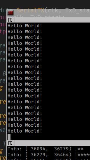 Hello World output from FPGA
My next steps is to make this work through network instead of serial port. Which would be really amazing!