QFH Antenna and my first reception of NOAA!
on
So in my last post I was playing with my RTL-SDR with an Intel Edison. So I decided to build a QFH Antenna to be able to receive NOAA APT Signals. These NOAA Weather Satellites broadcast an APT signal with about 5 to 8 Watts at 2m band, and considering how low this power is, it might surprise you that these signals arrive pretty strong at earth surface. But the biggest challenge to receive these signals are not its power. Its all about movement.
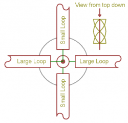
These satellites are sun-synchronous low orbit satellites, that means they aren’t locked to earth rotation. Instead, they actually do one turn on earth in about 1 hour and half. So whenever the satellite is in range of your receiver, it will appear on one side of the horizon, and disappear on another one. This creates a need for a good omni directional antenna that can receive signals from anywhere. But not only this: The signal is rotating (a.k.a. circular polarization)
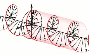
So we need a antenna that can receive circular polarized signals. We have a few choices like QFH (QuadriFiliar Helix) , Double Cross Antenna (Double Dipole) or Turnstyle Antenna.
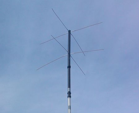
TurnStyle Antenna (Source: http://www.rtl-sdr.com/ )
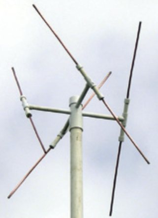
Double Cross Antenna (Source: http://www.rtl-sdr.com/ )
I decided to go for QFH because it was the easiest to be done with what I had.
Building the Antenna
So for building an antenna, I first started searching some previous experiences with QFH in the internet. I found this website http://www.jcoppens.com/ant/qfh/calc.en.php that have a pretty good calculator. To be honest I did not like much how the layout of the calculator is (I think it is very confusing) but it gets the right values and can even generate drilling templates. But later I will make my own calculator and drilling generator for that.
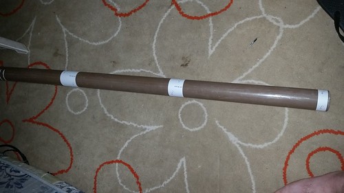
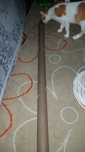
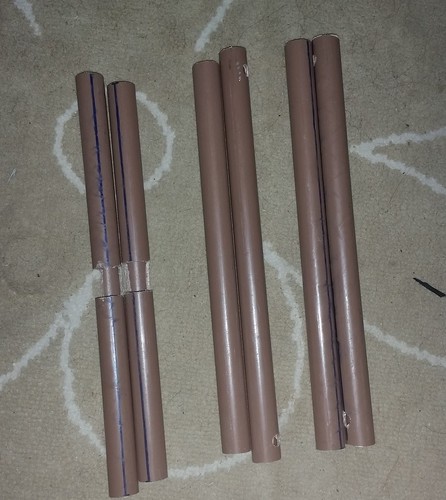
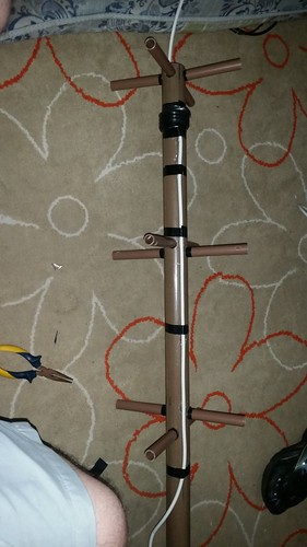
So the default parameters were very good for me, and I printed the drilling guides for my tubes. For the mast (vertical tube) I had to use a 2m x 5cm PVC Pipe (sewer pipe) and for the Horizontal tubes I had to use a 2cm diameter PVC tube (sewer pipe as well). I bought 2m of it as well and it was enough.
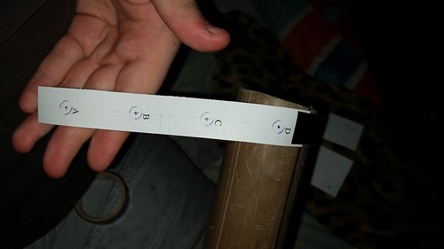
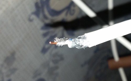
So as you can see, the drilling templates were only used for positioning. First I was thinking about using copper pipe to to the horizontal guides, but I decided to use the 2cm PVC Pipe instead. So I just drilled a bigger hole. In the picture above, my RGE-06 Coax Cable for the conductor (I wish I had a copper braid coax 🙁 )
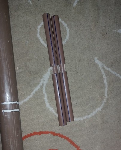
So the two top-most horizontal guides are on the same level, also is where the cables go out to I plug with the output. So I cut 80% of the pipe in the middle with the width of a pipe (so, 2cm). The two guides from the middle had to have holes in the ends so the Coax Cable passes through it.
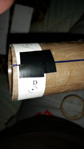
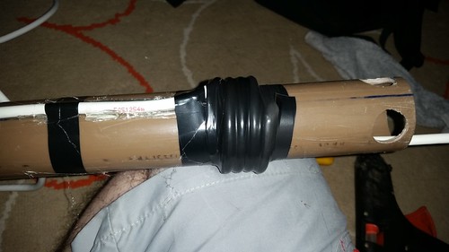
So first things first. I glued with hot glue and insulation tape the output cable on the side of the mast and drilled one additional hole at the top. This is needed because we need a 4 turn “balun” to match the unbalanced coax cable with a balanced antenna signal. So the hole was to pass the coax cable inside to exit on the top of the mast (so I can do the wirings there).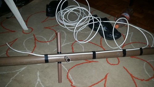
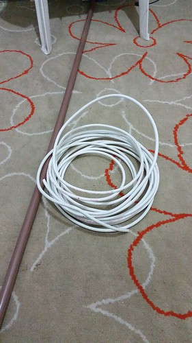
After that I started winding the antenna. So I had to cut two pieces of 2m coax cable to do the two loops of the antenna. Firstly I made a mistake doing Left Handed Polarization instead of Right Hand Polarization. So just to help you guys: Make your right hand a L shape with your fingers with your Thumb parallel with the antenna. If you rotate your hand in the direction of your fingers, and the cable follows the direction of your fingers, you have Right Hand Polarization. If it doesn’t, it will probably do with your Left hand. Make sure your antenna is Right Hand Polarized not left. The cables should go top to down when you rotate your hand. If you have any doubts, take a look on the next picture. So if you are thinking about how the cables goes inside these tubings, basically just imagine as a O shape loop, with the O cut at the top of the mast (so actually a U shape lol)
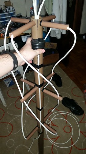
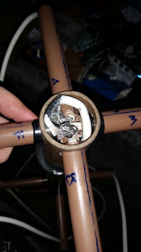
So here we have all 4 points + the output at the top.
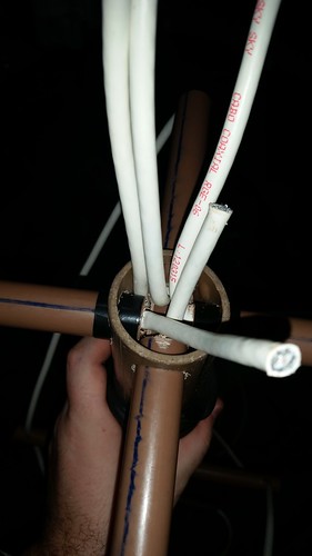
So it looks complicated to wire, but is not that hard. Take a look here:
So basically if you rotate the antenna that the conductors make an X, you wire the left side cables with the conductor of the output, and right side cables with braid of the output. Please notice that for the 4 cables that arrive at the top, you need to short circuit the conductor and the braid, so the entire cable will act like one conductor.
So this is what it looks after everything connected. I know it looks ugly, and thats why I wanted a copper braid coax cable :/
So after everything wired, the antenna looks like this: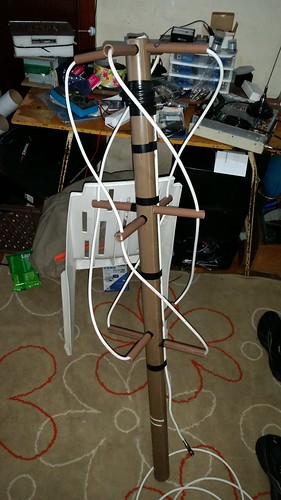
First Test
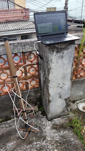
So just after I finished wiring everything up, I got my laptop, my SDR and my antenna and went out to test it on the first satellite that would pass. So besides the antenna is on the ground on the picture, I actually held the antenna still on the wall, pointing upwards. I got a good signal, but not for a long time because the antenna was too low and since there is a lot of houses (and even my roof was higher than the antenna) I did not get much of the horizon for it. So I went to fix it.
Fixing the antenna
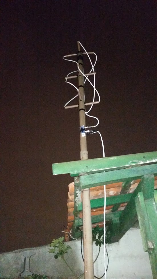
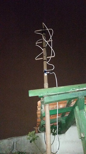
So I had to search a place on the roof to get the antenna fixed. So I found a corner that was perfect for that. Also I got a longer PVC Pipe and fixed on my antenna, so I could fix better.
So this is how it looks from the street.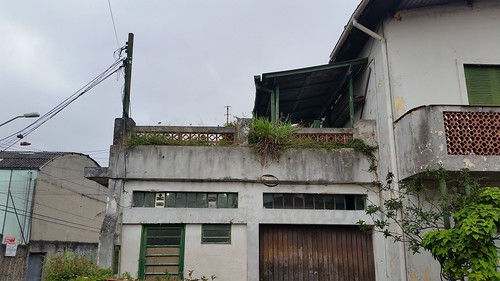
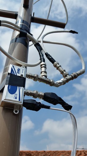
I also got a LNA (Low noise amplifier) in the antenna (you can see on the first picture) because I wanted the cable to go straight to my room, and this is about 10m of coax cable. I used a coax cable that have a power conductor on the side (it is used for Security Cameras, so you can pass power together with the signal). But I just noticed that the LNA had a too wide band (5 MHz to 1GHz) and this was amplifing as well the Floor Noise and Cross Band interference.
New Filters
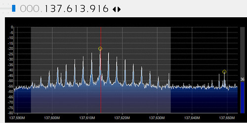
So I decided to start with a basic filter and then go to a better filter (which I didnt yet). The simplest way I thought was to try to remove the FM Radio Band (88 to 108MHz) and the 200MHz+ Band. The perfect filter for removing specific frequencies are the Notch Filters. I found a very simple notch filter that is done by using a piece of coax cable cut in 1/4 of the wavelength you want to strip out from your signal. So I made two coax notch filters: One for 106MHz and other for 270MHz. The 270MHz filter have a 135MHz pass band, and the 106MHz should attenuate the 88-108MHZ band a little. This should reduce my noise floor.
So before putting the filter at the antenna, I ran some tests here in my desk. The test were simple: I had the best Spectrum Analyzer I could have – The SDR. So I just got another LNA I had here and wired like this:
Random FM Radio Antenna => Filters => LNA => SDR
So in this way I could test how effective the Filter would be.Here is the result:
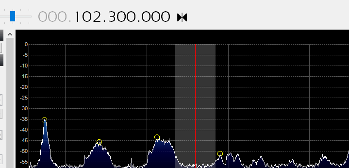
102MHz Band without the filter
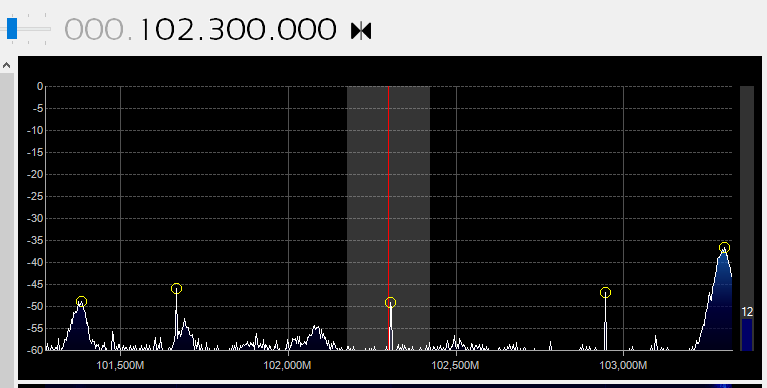
102MHz Band with the filter
Also, I had no attenuation at 135-138MHz band. So I decided to put the filter on the antenna.
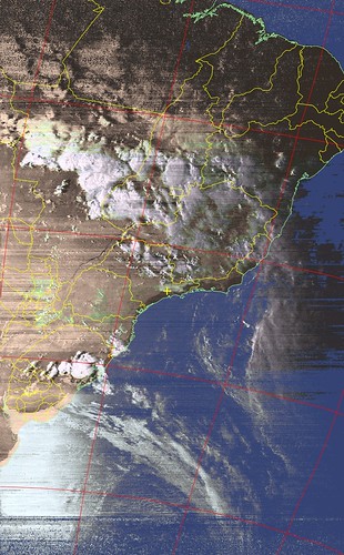
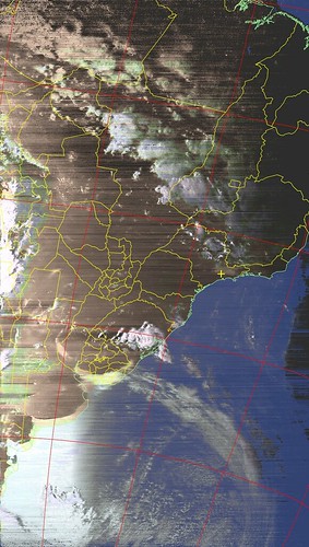
Tests and Results
So yesterday (24/01/2016, saturday) I saw that the NOAA Satellites would pass directly over my home, so I decided to power up the antenna and give a try. Here are the results ! 😀