New way to measure filters and my new filter
 Written by
Lucas Teske
on
So I’m still mad about the FM Spectrum (88-108MHz) noise I get when using a LNA or something else. So I’m still looking for a nice and easy way to filter out these signals.
Last time I posted about a TV/FM Diplexer, that works great, but doesn’t attenuate enough the signals. So the solution would be cascading several of them, but I found that is very hard to find one Diplexer or FM Trap filter those days.
So I started looking out how to make my own filters. So I reopened Adam’s Website (LNA4ALL) that have a small filter he did for FM Trap and tried (again) to make my own.
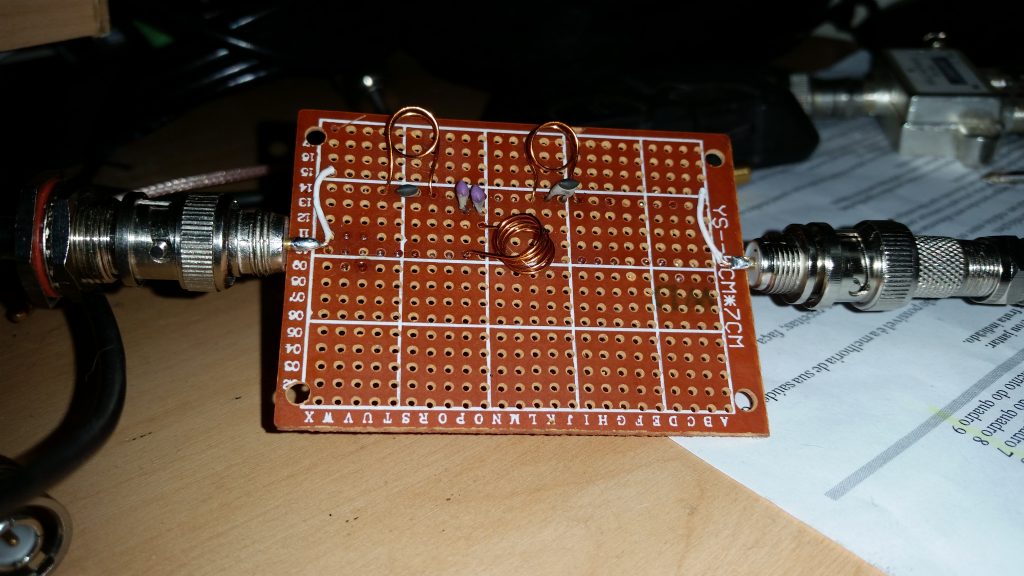
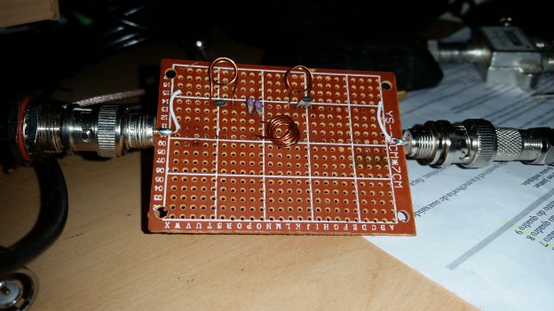
This time I tryed to find capacitores that actually matches the values that it was calculated. I found here 2 56pF caps and 2 47pF caps. The two 47 is to make in parallel so I would have something arround 23,5pF that is close enough for the center tap 20pF cap.
Also I found a coil of 0,35mm diameter wire here, that’s exactly what he used. I also got a Cooper Pipe to do the coil wind. So this is how the filter went out:
So first I tested with SDR# with a real receiving FM Band and my HackRF to have a good wide spectrum (20MHz). Here is what it looks without the filter:
And here is what it looks like with my filter:
I got impressed this time, because it really made a big difference. I also played with the coils stretching and compressing to change the center frequency. But as you can see, there are still some very high signals there. This generates a lot of background noise (in HackRF more than RTLSDR because of the IF Filters).
So I decided to find a better way to measure my filter response, since I don’t have a wideband noise generator. My idea was to go to GNU Radio and put my HackRF to generate a a wideband Noise signal. This could easily be done by putting a White Noise Source directly to Osmocom output. I also added a Slider to range the output frequency from 20MHz to 160MHz, so I can do a wide analysis of the filter.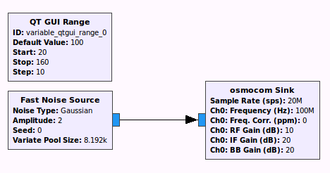
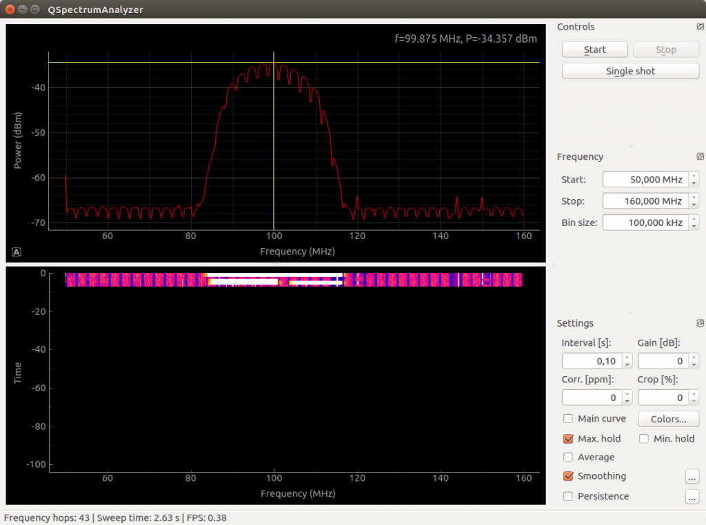
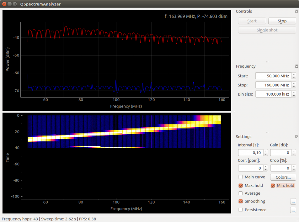
So first I wanted to setup a baseline profile of the HackRF Output in the spectrum. For that I just got the output of HackRF through a 3dB attenuator and to my RTLSDR. I used QSpectrumAnalyzer as before with the range from 50MHz to 160MHz and 100kHz steps. This time for some weird reason I got some notching at the QSpectrumAnalyzer between the frequency steps.
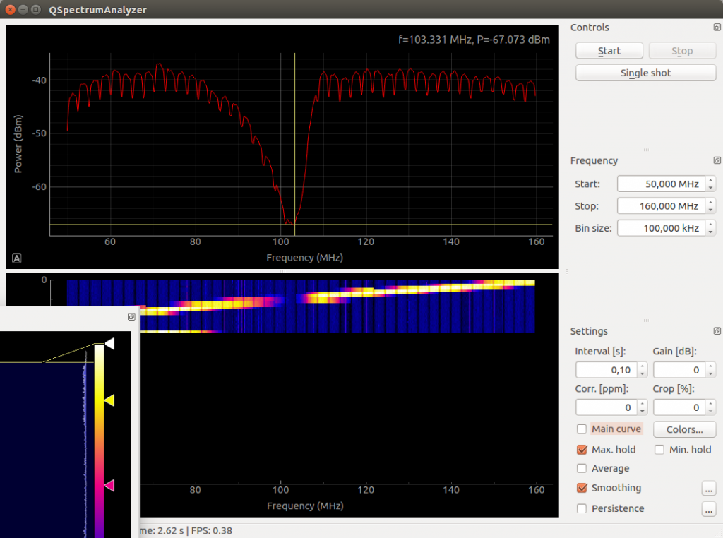
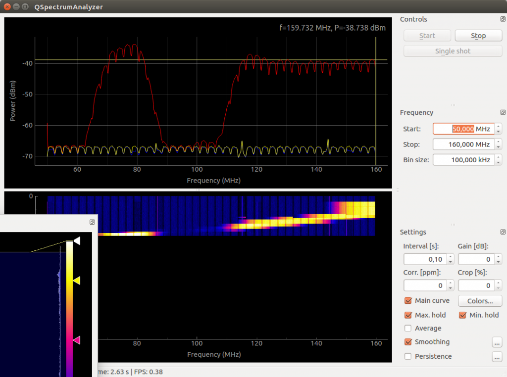
So my Output are not very linear (maybe because of the Attenuator, or the impedance mismatch (the HackRF is 50 Ohms and the RTLSDR is 75 Ohms), but still this will give a very good idea of how is the shape of the Filter Curve. So here it is:
So as you can see, my notch is at 103MHz. But sadly I still get moderated high signal at 106MHz (that still have some radio stations). The good thing is that this time I got it right, the bandwidth is from 88-108MHz, and since it is a 3-pole filter, it was expected to not have a very wide attenuation band. So by this new way of testing, I decided to re-test my TV/FM Diplexer, with this technique, so I could have a more precise curve. And here is the result:
So as you can see, the TV/FM Diplexer have a very wide band stop filtering and completes (-30dB) attenuates the FM Spectrum. So probably this filter is still my best way around. I hope I can make better filters in the future (I ordered a lot of capacitores with a lot of values so I can keep making better filters).
I hope this information is useful for you, reader. I will keep posting news about my Crusade against the FM Band

