em
Dish Feed (The actual receiver)
So I did several tries for like one month and half. The guys in #hearsat and me was struggling to find what was the reason that I couldn’t get the signal. I have all pictures of my failed feeds here: https://www.flickr.com/photos/energylabs/albums/72157675387388535. I will not detail each one of the assembles of these feeds because it didn’t work. So for historical reasons as well the reason why they didn’t work is because of the illumination angle of the Helical Coils. Usually the Helix Feeds have a very narrow beam width (and high gain), this causes to only some portion of the dish to be actually used by the feed. I only discovered that when I drawed my dish in FreeCad and did some auxiliary lines to show the angles. Then I noticed that something was REALLY wrong: Only like 60cm of my dish was actually illuminated, and from this 60cm only 40cm was actually visible by the dish (we need to discount the dead center). This is the drawing I did. So mybit from hearsat suggested me a Wave Guide Feed. For those that used to hack wireless systems, this is known as Can Antenna or Cantenna. Its very simple to do and I found this calculator to get things better:
http://www.changpuak.ch/electronics/cantenna.php
So the image (from the site) is this:
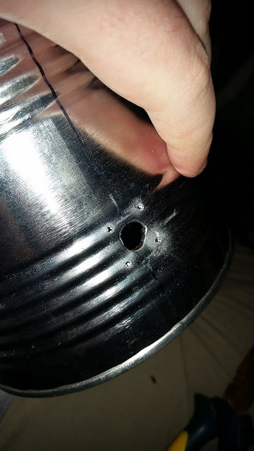
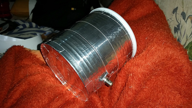
So if you check, the only thing that actually uses your target wavelength is the linear feed size (that uses lambda / 4). The other ones uselambdagthat is the guide wavelength. The guide wavelength is calculated from the can diameter. So I just found a can here (Neston Can for those who want to buy in São Paulo) that has basically “square” size. The can has 12cm diameter and 12cm height. You can use basically any size of cans. Just a few things are important using that calculator:
- Keep your target frequency over TE11 and below TM01.
- The length of the can should be at least 0.75 * lambdag. Don’t worry if your can length is higher than that. Just try to keep close.
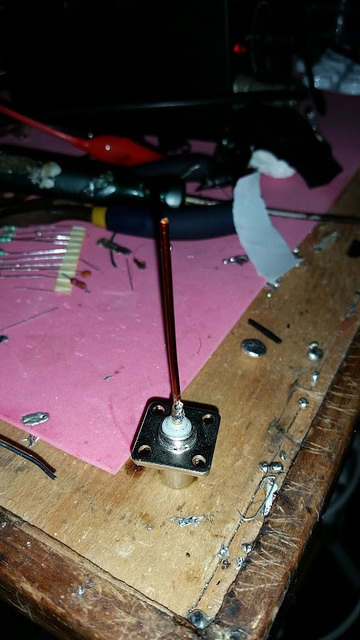
- The probe length (linear feed) counts from the base of the connector (where you put the screws)
More details about TE11 and TM01 are here: http://www.daenotes.com/electronics/microwave-radar/waveguide-modes-of-signal-propagation
In my case the parameters for the calculator was:
- Freq. of operation [MHz] 1692
- Can Diameter [mm] 120
- Cut-Off Freq. for TE11 Mode [MHz] 1464.15
- Cut-Off Freq. for TM01 Mode [MHz] 1912.38
- Guide Wavelength [mm] (λg) 153.89
- λg/4 [mm] 38.4725
- 0.75 * λg [mm] 115.4175
- Wavelength λ/4 [mm] 44.325
These wave guides usually have really wide bandwidth ( mine can probably get anything from TE11 to TM01 modes ). So the sizes are not that critical. Even so, I would keep the probe (the linear feed) length close to few mm of the lambda / 4 of the target frequency.