em
Convolution Encoding, Frame Synchronization and Viterbi
The first thing we need to do is sync our frame starts. For making easier to find the packet start, these bit streams has something called preamble. The preamble is basically a period when the bits sent does not actually contains any data, besides a information that informs the decoder that this is the frame start. Usually the preamble consists in a fixed 32 bits synchronization word. Most of the satellite systems use the standard CCSDS Synchronization Word that is 0x1ACFFC1D ( or in bits: 00011010 11001111 11111100 00011101). So basically we can use this to find where our data starts. After we find these 32 bits we will have the start of the data. Also with two sync words, we can find the period of our frame (or, how many bits the frame has). But things can never be that easy: The data is Convolution Encoded (including the Sync Word). Why is the data Convolution Encoded? That’s simple: Its a way to correct errors (bit swaps). So let me talk a bit of convolution encoding.
Convolution Encoding
Convolution Encoding basically is a process that generates parity of original data as the output. This parity has a special feature that is constructing a Trellis Diagram Sequence.

By Qef – Own work, Public Domain. https://commons.wikimedia.org/wiki/File:Convolutional_code_trellis_diagram.svg
A trellis diagram of two bits (as shown by the image), for every pair of bits, there is only two possible next two bits. For example if my pair is 00, the only possible next pair is 00 or 10. By convolution encoding a data, we generate parity that follows the Trellis diagram, in this way if we have errors in our bit stream, we can use a statistical way to find the most possible path in the trellis diagram that represents that data, then correcting the errors.
A trellis diagram of two bits (as shown by the image), for every pair of bits, there is only two possible next two bits. For example if my pair is 00, the only possible next pair is 00 or 10. By convolution encoding a data, we generate parity that follows the Trellis diagram, in this way if we have errors in our bit stream, we can use a statistical way to find the most possible path in the trellis diagram that represents that data, then correcting the errors.
So how actually the data is encoded? The image below will show a example of convolution encoder:
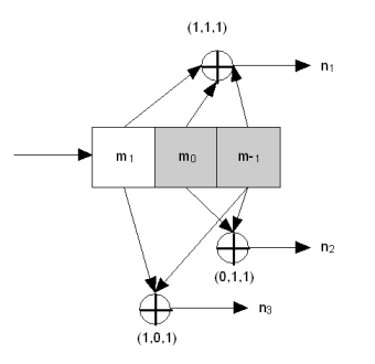
By Teridon at English Wikipedia - Own work (Teridon), Public Domain, https://commons.wikimedia.org/w/index.php?curid=12803371
The image shows a k=3,r=1/3 convolution encoder. The k parameter says how many bits our buffer has. For a k=3 we will have a buffer of 3 bits. The r parameter gives us the rate of the encoder, in other words, how many bits our encoder produces. In this case, for every 1 bit we input to the encoder, we generate 3 bits. The encoder in the image also has three more parameters: G1 = 111, G2 = 011, G3 = 101. These are the generator polynomials. It’s always one generator polynomial per bit of output. So for r = 1/2 we would have 2 polys, for 1/6 we would have 6 polys. And here is how the encoder works:
- The buffer starts with all 0 (unless specified different)
- The input bit enters on the left side of the buffer, and shifts all the buffer bits to the right.
- Each polymonial says what bits should be sum to give the corresponding parity bit.
- Cycle repeats.
So let me give an example. Suppose we’re already with thek buffer filled with101. Our next bit is 1. So we shift our buffer kright, and put our input bit on the left-most position. So our buffer now will have110. Now our 3 output bits will be:
- n0 = 1 + 1 + 0 = 0
- n1 = 0 + 1 + 0 = 1
- n2 = 1 + 0 + 0 = 1
So why these values? The generic way to represent that is:
- n0 = k[0] ^ G0[0] + k[1] ^ G0[1] + k[2] ^ G0[2]
- n1 = k[0] ^ G1[0] + k[1] ^ G1[1] + k[2] ^ G1[2]
- n2 = k[0] ^ G2[0] + k[1] ^ G2[1] + k[2] ^ G2[2]
Keep in mind, this is a mod 2 operation (we only have one bit output). So basically we just get every buffer kbits, xor with the corresponding position of the corresponding poly, and them sum to the output.
In this chapter we will use a lot of libfec routines to process our data. The first one is to encode the sync words.